Two-stage spring type tunnel detecting radar tray device

A detection radar and spring-type technology, which is applied in the field of tunnel radar detection, can solve the problems of being separated from the top lining surface or being hard pressed, labor-intensive, left and right deviation of the detection radar, etc., to achieve accurate and stable detection data, installation and removal. Simple and stable effect

Pending Publication Date: 2018-06-15
EAST CHINA JIAOTONG UNIVERSITY
View PDF7 Cites 3 Cited by
  • Summary
  • Abstract
  • Description
  • Claims
  • Application Information

AI Technical Summary

Problems solved by technology

There are many deficiencies in this detection method, such as poor safety of personnel, high labor intensity, inaccurate detection results and poor data stability, etc.
Although there is a method of installing tunnel detection radars on some telescopic mechanisms to replace manual lifting, which solves the problems of safety and labor intensity of manual lifting, these telescopic mechanisms are not flexible, and the detection radar and the tunnel roof lining surface are actually It is a hard top. When the road surface is uneven, the top lining surface is uneven or the inspection vehicle is bumpy, if the height of the telescopic mechanism is adjusted without stopping the machine, the tunnel detection radar will be detached from the top lining surface or be hard pressed, resulting in inaccurate and unstable detection data Or the detection radar is crushed; in addition, it is impossible for the detection vehicle to keep driving in a straight line during the detection process. When the detection vehicle "snakes" or turns, it will cause the detection radar to shift left and right, and it will also cause the detection radar to fall off or hard top lining On the surface, it will also cause unstable and inaccurate detection results or adverse consequences of the detection radar being crushed

Method used


Image

  • Two-stage spring type tunnel detecting radar tray device
  • Two-stage spring type tunnel detecting radar tray device
  • Two-stage spring type tunnel detecting radar tray device

Examples


Embodiment Construction

[0020] Embodiments of the present invention will be further described below in conjunction with the accompanying drawings.

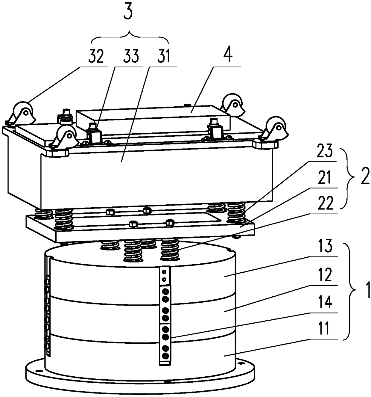
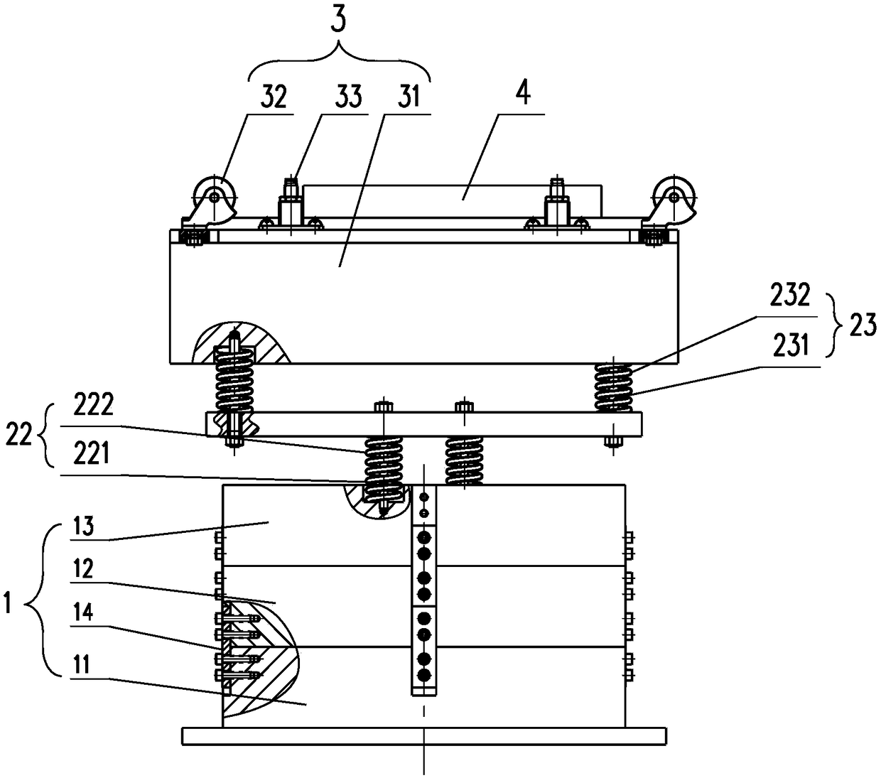
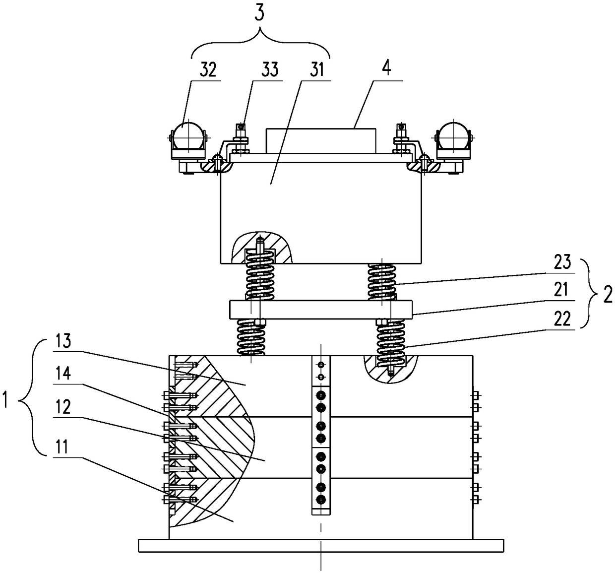
[0021] Such as Figure 1-4 As shown, a dual-stage spring-type tunnel detection radar tray device includes a bottom height adjustment support 1, an elastic self-adaptive mechanism 2, a loading mechanism 3 and a detection radar 4;

[0022] The bottom height-adjusting support 1, the elastic adaptive mechanism 2 and the loading mechanism 3 are arranged in sequence from bottom to top, and the loading mechanism 3 is connected to the bottom height-adjusting support 1 through the elastic adaptive mechanism 2;

[0023] The elastic adaptive mechanism 2 includes a spring transition bracket 21, several hard spring assemblies 22 and several soft spring assemblies 23, and the hard spring assembly 22 includes a hard spring guide rod 221 and is sleeved on the hard spring guide rod 221. The hard spring 222 on the top, the soft spring assembly 23 includes a soft spring g...


PUM


Abstract

The invention discloses a two-stage spring type tunnel detecting radar tray device which comprises a bottom part height adjusting support, an elastic self-adaptive mechanism, a load receiving mechanism and a detecting radar; the elastic self-adaptive mechanism comprises a spring transition support rack, a number of hard spring assemblies and a plurality of soft spring assemblies; the spring transition support rack is positioned between the hard spring assembly and the soft spring assembly. The device disclosed in the invention is advantaged by compact structure, simple operation, convenient installation, strong applicability, and particular suitability for installation and fixation of the detecting radar during detection of a surface of a tunnel top lining; the elastic self-adaptive mechanism is arranged to ensure that the load receiving mechanism can be in contact with the surface of the top lining all along and constant contact force can be kept during a tunnel detecting process whenthe surface of the tunnel top lining is not flat, a road surface is uneven, and a detection car bumps along or slither; distance between the detection radar and the surface of the top lining can be kept from being changed or the detection radar and the surface of the top lining can be prevented from being crushed by the hard top, and that the detection process can be carried out smoothly and thatthe detection data is accurate and stable can be ensured.

Description

technical field [0001] The invention belongs to the technical field of tunnel radar detection, in particular to a dual-stage spring-type tunnel detection radar tray device. Background technique [0002] At present, in the process of non-destructive testing of the quality of tunnel roof lining concrete, the inspection of the roof lining surface is mainly carried out by people standing on the vehicle and holding the tunnel detection radar with both hands. There are many deficiencies in this detection method, such as poor safety of personnel, high labor intensity, inaccurate detection results and poor data stability. Although there is a method of installing tunnel detection radar on some telescopic mechanisms to replace manual lifting, which solves the problems of safety and labor intensity of manual lifting, these telescopic mechanisms are not flexible, and the detection radar and the tunnel roof lining surface are actually It is a hard top. When the road surface is uneven, t...

Claims


Application Information

Patent Timeline
Patent Type & Authority Applications(China)
IPC IPC(8): G01S7/02
CPCG01S7/02
Inventor 刘乐平彭玲阳曾昭韦陈金华舒盛荣李林吴志琴
Owner EAST CHINA JIAOTONG UNIVERSITY
Why Eureka
Try Eureka