
Optical compensation film, mask and exposure machine

一种光学补偿膜、曝光机的技术,应用在微光刻曝光设备、光学、照相制版工艺曝光装置等方向,能够解决降低显示性能、基板2曝光强度不均匀等问题,达到提高显示性能、提高光的强度、曝光强度均匀的效果

Active Publication Date: 2018-06-15
WUHAN CHINA STAR OPTOELECTRONICS TECH CO LTD
View PDF9 Cites 2 Cited by
  • Summary
  • Abstract
  • Description
  • Claims
  • Application Information

AI Technical Summary

Problems solved by technology

Since the light intensity E1' emitted through the prism overlapping position 11 is smaller than the light intensity E2' emitted through the prism non-overlapping position 12, the exposure intensity of the substrate 2 will be uneven and the display performance of the LCD will be reduced.

Method used


Image

  • Optical compensation film, mask and exposure machine
  • Optical compensation film, mask and exposure machine
  • Optical compensation film, mask and exposure machine

Examples


Embodiment Construction

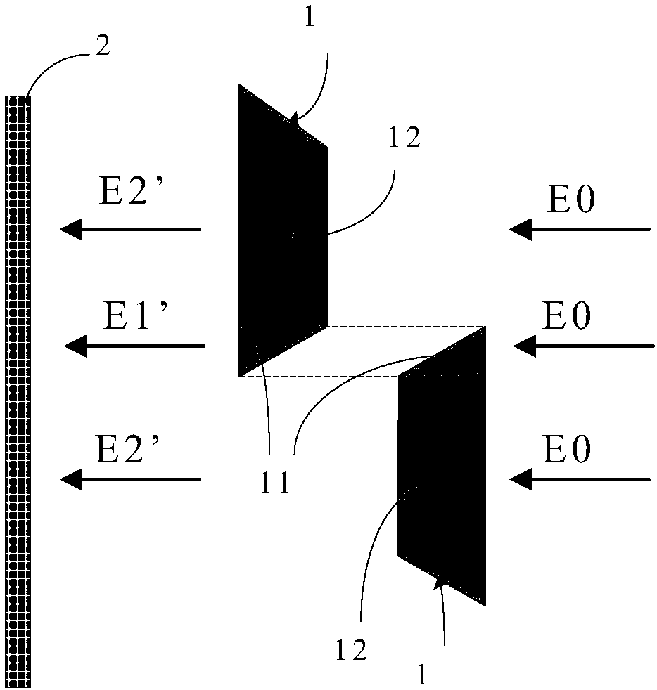
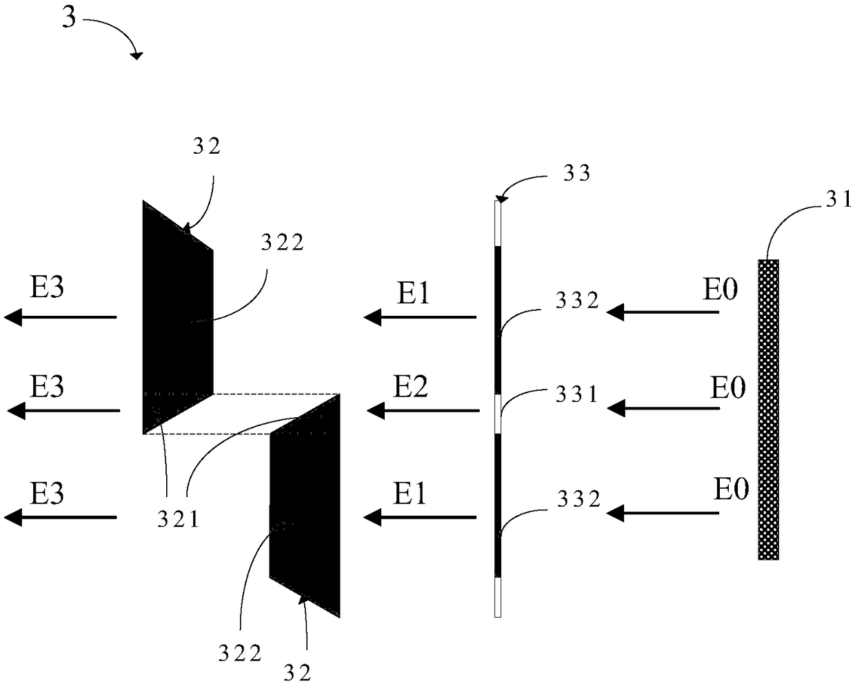
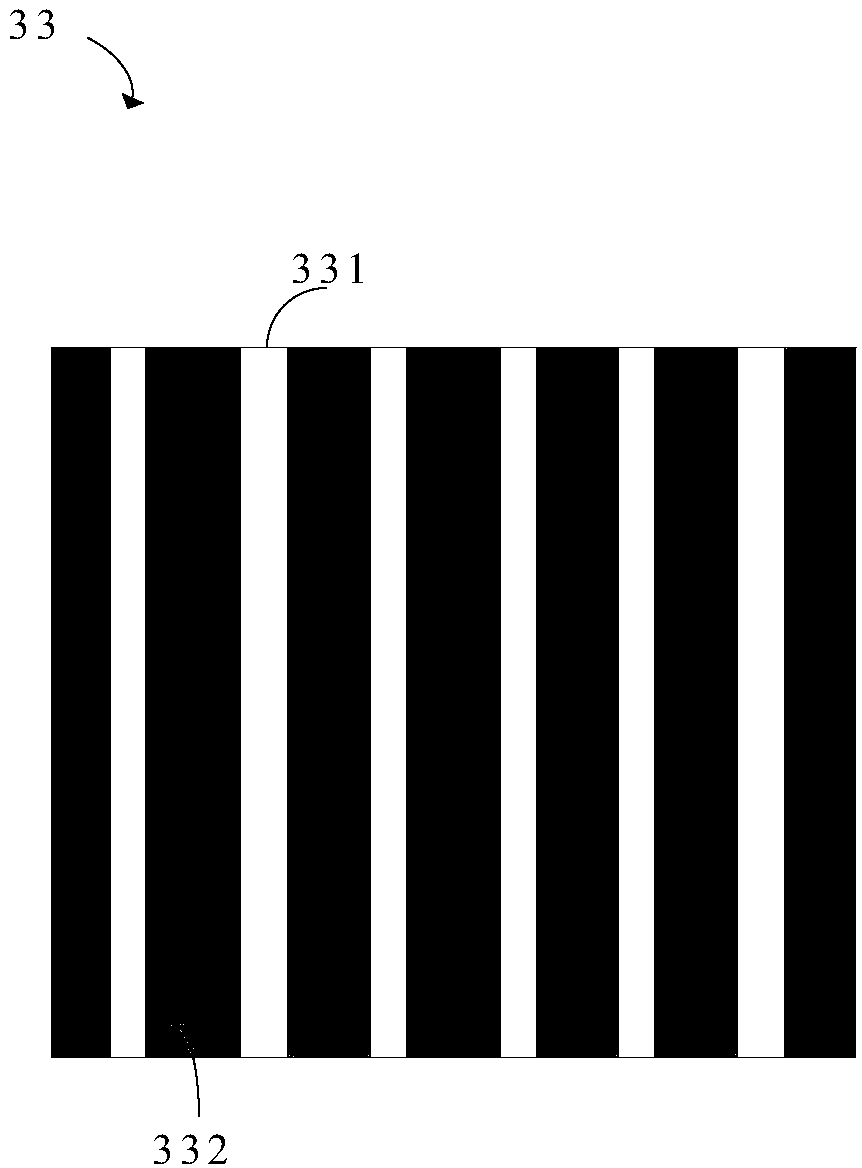
[0031] The following descriptions of the various embodiments refer to the accompanying drawings to illustrate specific embodiments in which the present invention can be practiced. The directional terms mentioned in the present invention, such as "up", "down", "front", "back", "left", "right", "inside", "outside", "side", etc., are for reference only The orientation of the attached schema. Therefore, the directional terms used are used to illustrate and understand the present invention, but not to limit the present invention.

[0032] In the figures, structurally similar units are denoted by the same reference numerals.

[0033] Reference herein to an "embodiment" means that a particular feature, structure, or characteristic described in connection with the embodiment can be included in at least one embodiment of the present invention. The occurrences of this phrase in various places in the specification are not necessarily all referring to the same embodiment, nor are separa...


PUM


Abstract

The invention provides an optical compensation film, a mask and an exposure machine. The optical compensation film is used for the exposure machine, the exposure machine comprises several prisms, adjacent two prisms are overlapped, an overlap part and a non-overlap part are formed, the optical compensation film comprises a first area optical compensation film and a second area optical compensationfilm; the first area optical compensation film and the overlap part of the prisms are oppositely arranged, and the first area optical compensation film is used for transmitting light to the overlap part of the prisms; the second area optical compensation film and the non-overlap part of the prisms are oppositely arranged, and the second area optical compensation film is used for transmitting light to the non-overlap part of the prisms, wherein the light transmittance rate of the first area optical compensation film is greater than the light transmittance rate of the second area optical compensation film. The scheme is characterized in that the light transmittance rate of the first area optical compensation film is greater than the light transmittance rate of the second area optical compensation film, luminous intensity of the different parts through the prism is same, uniformity of an exposure film is guaranteed, and the display performance of a display panel is increased.

Description

technical field [0001] The invention relates to the field of display technology, in particular to an optical compensation film, a mask plate and an exposure machine. Background technique [0002] A liquid crystal display panel (Liquid crystal display, LCD) occupies a mainstream position in the field of display technology due to its advantages of high chromaticity and low energy consumption. [0003] In the LCD manufacturing process, an exposure machine is usually used to transfer the pattern on the mask plate to the glass substrate. Among them, the Nikon exposure machine is widely used because of its advantages of high precision and large adjustment range. [0004] Such as figure 1 As shown, the Nikon exposure machine adopts the exposure mode during scanning, and the light with the intensity E0' passes through a group of partially overlapping prisms 1, and then hits the surface of the substrate 2 to complete the exposure. Since the light intensity E1' emitted through the ...

Claims


Application Information

Patent Timeline
Patent Type & Authority Applications(China)
IPC IPC(8): G03F1/38G03F7/20
CPCG03F1/38G03F7/7015G03F7/70275G03F7/70308G03F7/70983B29D11/00788
Inventor 熊兴
Owner WUHAN CHINA STAR OPTOELECTRONICS TECH CO LTD
Learn More