A method for calculating pretension of shaped mesh antenna

A calculation method and pre-tension technology, applied in design optimization/simulation, special data processing applications, etc., can solve problems such as the inability to realize electromagnetic wave reflection mesh surface tension, and achieve the effect of broad market application prospects, smooth logic, and clear thinking

Active Publication Date: 2021-12-07
XIAN INSTITUE OF SPACE RADIO TECH
View PDF3 Cites 0 Cited by
  • Summary
  • Abstract
  • Description
  • Claims
  • Application Information

AI Technical Summary

Problems solved by technology

[0004] The existing pretension calculation methods are all for the mesh antenna with double-layer cable net structure. The mesh surface is a parabolic surface, and the rope units only bear the tension. Therefore, the traditional pretension algorithm cannot realize the electromagnetic wave reflection of some nodes on the mesh surface. tension at negative

Method used


Image

  • A method for calculating pretension of shaped mesh antenna
  • A method for calculating pretension of shaped mesh antenna
  • A method for calculating pretension of shaped mesh antenna

Examples


Embodiment Construction

[0053] In order to make the solution of the present invention clearer, the present invention will be further described below in conjunction with the accompanying drawings and specific embodiments:

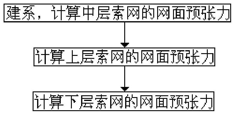
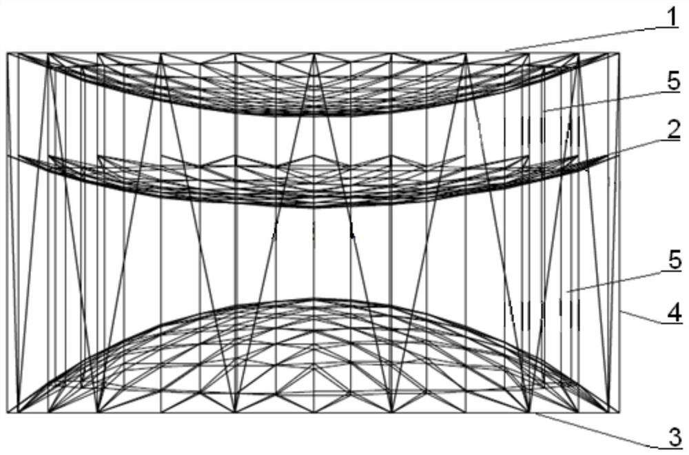
[0054] Such as Figure 1~2 As shown, a method for calculating the pretension of a shaped mesh antenna, the shaped mesh antenna includes an upper cable net 1, a middle cable net 2, a lower cable net 3, a truss 4 and a rope 5; the truss 4 adopts a hollow cylindrical shape The frame structure has an upper cable net 1, a middle cable net 2 and a lower cable net 3 in sequence in the axial direction, and the nodes of the upper cable net 1 and the lower cable net 3 are connected to the nodes of the middle cable net 2 through ropes 5. To maintain the shape of the middle cable network 2 mesh surface; its calculation method includes the following steps:

[0055] S1: Taking the center of truss 4 as the reference, the axial direction of truss 4 as the z-axis, and the radial direction of truss...


PUM


Abstract

The invention discloses a method for calculating the pretension of a shaped mesh antenna, which is used for calculating the pretension of mesh elements of a space shaped mesh antenna unfolded structure or a space shaped mesh antenna non-expanded structure, comprising the following steps: using a truss Based on the center, take the truss axis as the z-axis, and the truss radial direction as the x-axis, use the right-hand rule to establish the x, y, z-axis space Cartesian coordinate system, and calculate the middle layer cable net according to the preset average pretension Mesh surface pretension: calculate the mesh pretension of the upper layer cable net according to the mesh surface pretension of the middle layer cable net; The present invention calculates the tension of the three-layer shaped mesh antenna, so that different regions of the electromagnetic wave reflection net have certain concavo-convexity, and makes up for the defects of the traditional pretension calculation method.

Description

technical field [0001] The invention relates to a pretension calculation method of a shaped mesh antenna, which is especially suitable for near-earth satellite detection and belongs to the technical field of antenna profile design. Background technique [0002] Due to the continuous advancement of aerospace science and technology, space activities such as manned spaceflight and deep space exploration have put forward higher requirements for spaceborne antenna reflectors, such as larger diameter, high surface accuracy, high storage ratio, and lighter weight. However, due to the limitation of the carrying capacity of the vehicle, large-volume antennas cannot be placed in the load compartment. Therefore, large-scale spaceborne antennas often use deployable structures to solve this problem. At present, the process of assembling and testing the deployable antenna is mainly done on the ground. When the spacecraft is launched, the deployable antenna is folded and installed in the f...

Claims


Application Information

Patent Timeline
Patent Type & Authority Patents(China)
IPC IPC(8): G06F30/20
CPCG06F30/20
Inventor 李欢笑范叶森马小飞郑士昆龚博安葛兴涛王海涛张大为张旭涛
Owner XIAN INSTITUE OF SPACE RADIO TECH
Why Eureka
Try Eureka