Automatic inflatable football

An automatic inflation and football technology, applied in the field of sporting goods, can solve problems such as insufficient air pressure, difficulty in controlling inflation pressure, poor hardness and elasticity, etc., and achieve the effect of simple structure, good sports performance, and accurate center of gravity position

Active Publication Date: 2018-06-19
李智勇
View PDF6 Cites 5 Cited by
  • Summary
  • Abstract
  • Description
  • Claims
  • Application Information

AI Technical Summary

Problems solved by technology

The former has poorer hardness and elasticity, but is safer, and is more suitable for preschool children to use as toys. The latter has slightly better hardness and elasticity than the former, but excessively increases the weight and instability of the ball. air-filled football comparable to
However, the traditional football will have insufficient air pressure after being placed for a long time or used for a period of time. It is necessary to use the pump to inflate from time to time. At the same time, the inflation pressure is not easy to control, which affects the use effect.

Method used


Image

  • Automatic inflatable football
  • Automatic inflatable football
  • Automatic inflatable football

Examples


Embodiment 1

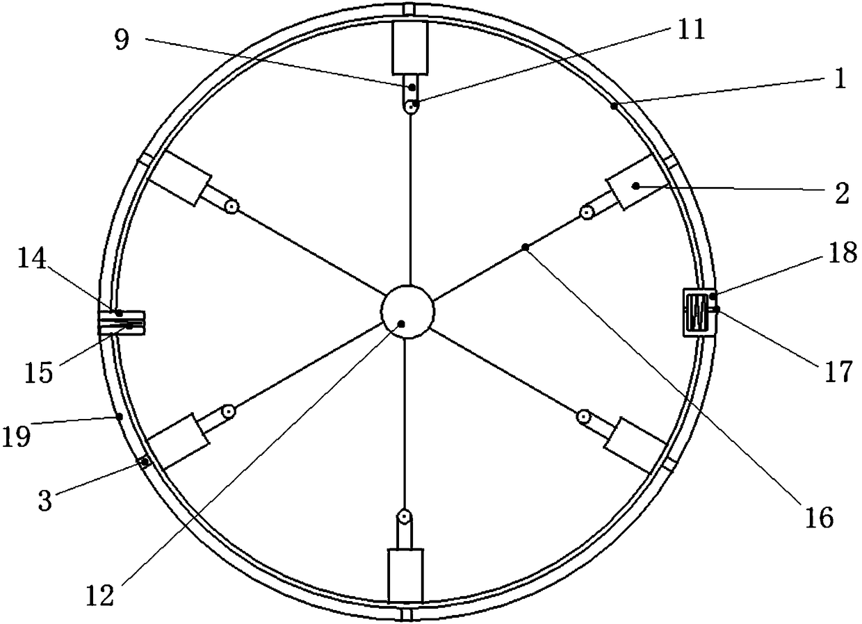
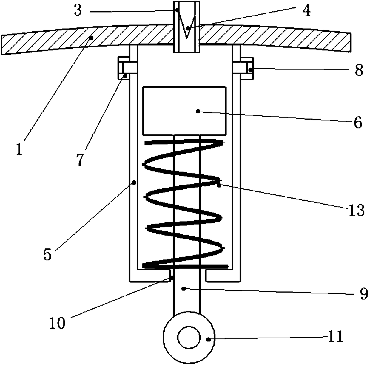
[0016] see figure 1 , figure 2 , image 3 , the self-inflating football includes a flexible hollow bladder 1, and a number of pumps 2 evenly distributed on the inner wall of the bladder 1. The first one-way valve 4 that prevents air from leaking out. The air pump 2 includes a cylinder 5 and a piston 6, the cylinder 5 is vertically connected to the inner wall of the bladder 1, and the center of the connection area between the cylinder 5 and the bladder 1 is provided with an air inlet 3 connected to the outside of the bladder 1, the air inlet 3 is provided with a first one-way valve 4 that prevents air from being discharged to the outside of the bladder 1, and the side wall of the cylinder 5 near the inner wall of the bladder 1 is provided with an exhaust hole 7, and an exhaust hole 7 is provided to prevent gas from entering the cylinder. The second one-way valve 8 inside the barrel 5. The cylinder 5 is provided with a piston 6 coaxial with the cylinder 5, the piston 6 move...

Embodiment 2

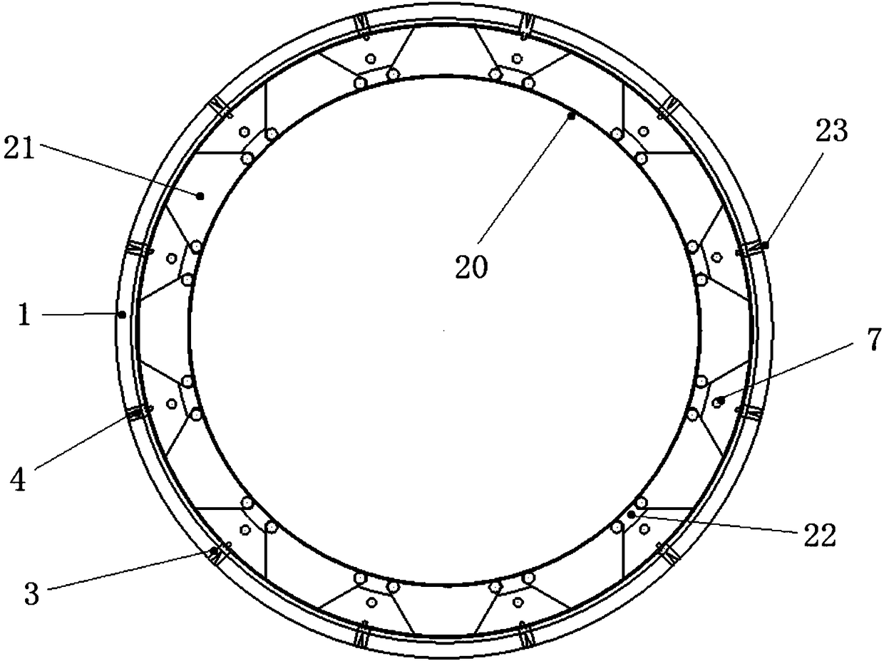
[0022] The self-inflating soccer ball provided in this embodiment includes a bladder 1, an annular duct 20 disposed inside the bladder 1, and several plungers distributed and connected between the bladder 1 and the annular duct 20 21. Each of the plungers 21 divides the space between the annular duct 20 and the bladder 1 into several subspaces, and the annular duct 20 corresponding to each subspace is provided with a vent hole 7, and the vent hole 7 is connected to the The interior of the annular duct 20 is communicated.

[0023] Its working principle is: when adopting the scheme of the circular pipe 20 to realize automatic inflation, the self-inflating soccer ball is deformed by external force, causing the circular pipe 20 to lose its circle. After the circular pipe 20 loses its circle, the distance between the inner plungers 21 changes. Wherein, when two adjacent plungers 21 become closer, the gas in the space of the annular duct 20 isolated therebetween can be pressed into ...


PUM


Abstract

The invention relates to the field of sporting goods, and particularly relates to an automatic inflatable football. The automatic inflatable football is mainly composed of a flexible hollow bladder and a plurality of inflators uniformly distributed on the inner wall of the bladder, air inlets communicated with the outside of the bladder are formed in the inflators, first one-way valves for preventing air leakage are arranged in the air inlets, and when the automatic inflatable football is used, the inflators suck the outside air into the inside of the bladder due to the inertia to achieve thefunction of automatic inflation.

Description

technical field [0001] The invention relates to the field of sporting goods, in particular to a self-inflating football. Background technique [0002] Most of the existing non-inflatable footballs are filled with PU foam or supported by an internal skeleton. Both of these methods are only suitable for use as toys, and are not suitable for formal school physical education courses or game balls. The former has poorer hardness and elasticity, but is safer, and is more suitable for preschool children to use as toys. The latter has slightly better hardness and elasticity than the former, but excessively increases the weight and instability of the ball. Comparable to an air-filled soccer ball. However, the air pressure will be insufficient after the traditional football is placed for a long time or used for a period of time. It is necessary to use the pump to inflate from time to time. At the same time, the inflation pressure is not easy to control, which affects the use effect. ...

Claims


Application Information

Patent Timeline
Patent Type & Authority Applications(China)
IPC IPC(8): A63B41/12A63B41/00
CPCA63B41/00A63B41/12
Inventor 刘占美李嘉李智勇
Owner 李智勇
Why Eureka
Try Eureka