
Automatic cutoff device for heat shrinkage sleeve

An automatic cutting and heat-shrinkable sleeve technology, which is applied in metal processing and other directions, can solve the problems of increasing manpower and labor intensity of workers

Inactive Publication Date: 2018-06-19
王文奎
View PDF0 Cites 11 Cited by
  • Summary
  • Abstract
  • Description
  • Claims
  • Application Information

AI Technical Summary

Problems solved by technology

[0003] At present, the processing of heat-shrinkable sleeves for wires is entirely manual. The heat-shrinkable sleeves are manually cut off according to the required length, and then the wires are inserted into the heat-shrinkable sleeves, and the heat-shrinkable sleeves are cut off manually. Inserting the wire into the heat-shrinkable sleeve requires a lot of manpower, and working for a long time will also bring greater labor intensity to the workers.

Method used


Image

  • Automatic cutoff device for heat shrinkage sleeve
  • Automatic cutoff device for heat shrinkage sleeve
  • Automatic cutoff device for heat shrinkage sleeve

Examples


Embodiment Construction

[0026] Below in conjunction with accompanying drawing and embodiment of description, specific embodiment of the present invention is described in further detail:

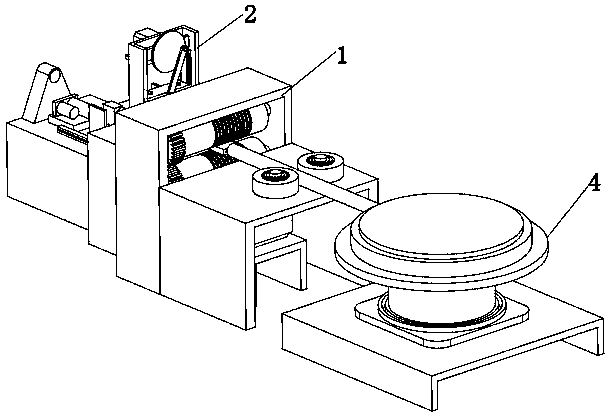
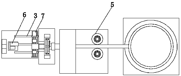
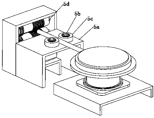
[0027] refer to Figure 1 to Figure 9 A heat-shrinkable sleeve automatic cutting device shown includes a feeding mechanism 1, a material cutting mechanism 2 and a pipe threading mechanism 3, and the material cutting mechanism 2 is located between the feeding mechanism 1 and the pipe threading mechanism 3, so The feeding mechanism 1 includes a stocking assembly 4 and a feeding assembly 5, the feeding assembly 5 is located between the stocking assembly 4 and the cutting mechanism 2, and the cutting mechanism 2 includes a support frame 2a, a cutting knife 2b and a driving assembly 8 for driving the cutting knife 2b to cut the workpiece, the driving assembly 8 is located on the top of the support bracket 2a, the cutting knife 2b is located directly above the support bracket 2a, and the cutting mechanism 2 also includes ...


PUM


Abstract

The invention relates to the technical field of mechanical devices, in particular to an automatic cutoff device for a heat shrinkage sleeve. The device comprises a feeding mechanism, a cutting mechanism and a tube penetrating mechanism, the cutting mechanism is located between the feeding mechanism and the tube penetrating mechanism, the feeding mechanism comprises a storage assembly and a feedingassembly, the feeding assembly is located between the storage assembly and the cutting mechanism, the cutting mechanism comprises a bearing frame, a cutter and a driving assembly, the driving assembly is located on the top of the bearing frame, the cutter is located over the bearing frame, the cutting mechanism further comprises two U-shaped limiting plates, the U-shaped limiting plates are arranged on the top of the bearing frame at an equal interval, and the tube penetrating mechanism comprises a tube penetrating assembly and a material supply assembly. Workpieces can be automatically cut off through the cutting mechanism, wire tube penetrating work can be automatically completed through the tube penetrating mechanism, manpower input is lowered, and labor intensity of workers is relieved.

Description

technical field [0001] The invention relates to the technical field of mechanical devices, in particular to an automatic cutting device for heat-shrinkable sleeves. Background technique [0002] Heat shrinkable sleeves, also known as heat shrinkable protective sleeves, provide insulation protection for wires, cables and wire terminals. It has high temperature shrinkage, softness, flame retardancy, insulation and corrosion protection, etc., and is widely used in insulation protection of various wire harnesses, solder joints, and inductors, as well as rust and corrosion protection of metal pipes and rods. [0003] At present, the processing of heat-shrinkable sleeves for wires is entirely manual. The heat-shrinkable sleeves are manually cut off according to the required length, and then the wires are inserted into the heat-shrinkable sleeves, and the heat-shrinkable sleeves are cut off manually. Inserting the wire into the heat-shrinkable sleeve requires a lot of manpower, an...

Claims


Application Information

Patent Timeline
IPC IPC(8): B26D1/08B26D3/16B26D7/08B26D7/27B29C63/42
CPCB26D1/08B26D3/168B26D7/08B26D7/27B29C63/42
Inventor 王文奎
Owner 王文奎
Learn More