Constant force device based on air spring and use method of constant force device

A technology of constant force device and air spring, which is applied in the field of constant force device, can solve the problems of low friction, low damping, low stiffness, etc., and achieve the effects of fast response, improved precision, and accurate pressure compensation

Active Publication Date: 2018-06-19
BEIJING SATELLITE MFG FACTORY
View PDF7 Cites 4 Cited by
  • Summary
  • Abstract
  • Description
  • Claims
  • Application Information

AI Technical Summary

Problems solved by technology

[0004] The technical problem to be solved by the present invention is: to overcome the deficiencies of the prior art, the present invention provides a constant force device based on an air spring, which solves the problem of introducing Due to the lack of external constraints and additional mass, the present invention is based on air pressure control and has a certain bearing capacity, and is an air constant force device with low stiffness, low damping and low friction

Method used


Image

  • Constant force device based on air spring and use method of constant force device
  • Constant force device based on air spring and use method of constant force device
  • Constant force device based on air spring and use method of constant force device

Examples


Embodiment Construction

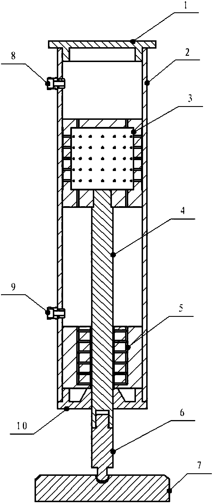
[0024] Such as figure 1 , figure 2 As shown, a constant force device based on an air spring includes a mechanism adapter 1, a cylinder body 2, an air suspension piston 3, a piston rod 4, an air bearing 5, a screw rod 6, and an air bearing 7. Air plugs 8, 9 and air bearing block 10.

[0025] The mechanism adapter 1 is the installation interface of the space mechanism, which is connected with the cylinder body 2 through threaded connection or adhesive connection, and at the same time ensures the airtightness of the connection; the air-suspended piston 3 is a hollow cavity structure, 2 Clearance fit is the moving part in the device. There are several throttle holes in the radial layout, and several throttle hole air supply channels in the axial layout. It is connected with the piston rod 4 through threads. The air suspension piston 3 radial The orifice connects the cavity in the air suspension piston 3 with the side wall, and the air supply passage of the throttle hole in the ...


PUM


Abstract

A constant force device based on an air spring comprises a mechanism adapter piece (1), a cylinder body (2) and the like. The mechanism adapter piece (1) is installed at one end of the cylinder body (2), and an air floating supporting stop block (10) is installed at the other end of the cylinder body (2); an air-suspending piston (3) is installed in the cylinder body (2); an air floating support (5) is fixedly installed in the cylinder body (2) and axially limited through the air floating supporting stop block (10), one end of a piston rod (4) is connected with the air-suspending piston (3), the other end of the piston rod (4) sequentially penetrates through the air floating support (5) and the air floating supporting stop block (10) and then is connected with an air floating bearing (7) through a screw (6); and a first air inflow plug (8) and a second air inflow plug (9) are installed on the portions, on the two sides of the air-suspending piston (3), of the side wall of the cylinderbody (2). The constant force device is based on air pressure control, has certain bearing capacity and is an air constant force device which is low in rigidity, damping and friction.

Description

technical field [0001] The invention relates to a constant force device. Background technique [0002] In order to ensure the authenticity of the ground adjustment and test of the space mechanism, it is necessary to simulate the space microgravity environment on the ground. When performing space mechanism assembly and adjustment tests on the ground, in addition to ensuring that the mechanism is in a microgravity state, it is also required that the mechanism is in a free state. [0003] At present, the ground microgravity simulation of space agencies adopts the method of gravity unloading tooling to compensate gravity to realize the microgravity state simulation, which introduces constraints or external interference while realizing microgravity, which seriously affects the vibration mode of the product; at the same time, too much additional mass is introduced , will also affect the frequency vibration characteristics of the space mechanism. Therefore, the ground assembly an...

Claims


Application Information

Patent Timeline
Patent Type & Authority Applications(China)
IPC IPC(8): B64G7/00G01M99/00
CPCB64G7/00G01M99/005
Inventor 李德勇张加波刘济洲于震鲁利刚孙璨姚旗程泽赵琳娜李海月
Owner BEIJING SATELLITE MFG FACTORY
Why Eureka
Try Eureka