
Air conditioning unit joint debugging fixture system and control method thereof

An air-conditioning unit and joint debugging technology, which is applied in the direction of measuring devices, machine/structural component testing, instruments, etc., can solve the problems of poor stability and reliability, less lubricating oil in compressors, etc., and achieve shortening Effects of length, stable oil return, improved stability and reliability

Active Publication Date: 2018-06-19
SHENZHEN ITEAQ NETWORK POWER TECH CO LTD
View PDF10 Cites 0 Cited by
  • Summary
  • Abstract
  • Description
  • Claims
  • Application Information

AI Technical Summary

Problems solved by technology

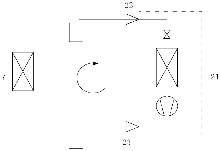
[0003] figure 1 The application scheme of the joint debugging system shown will have the following problems: Since the debugging position of the indoor unit 21 is located in the production line, for large air-conditioning units, the supporting condenser 7 is relatively large in size. The required condenser 7 is usually placed on the roof, therefore, the connecting pipeline of the whole joint debugging system is relatively long
Therefore, the oil return of the compressor will be unstable during the joint debugging process, and the air conditioner unit after commissioning will have more or less lubricating oil in the compressor. For the oil-deficient unit, the stability and reliability of the air conditioner unit after leaving the factory will deteriorate

Method used


Image

  • Air conditioning unit joint debugging fixture system and control method thereof
  • Air conditioning unit joint debugging fixture system and control method thereof
  • Air conditioning unit joint debugging fixture system and control method thereof

Examples


Embodiment Construction

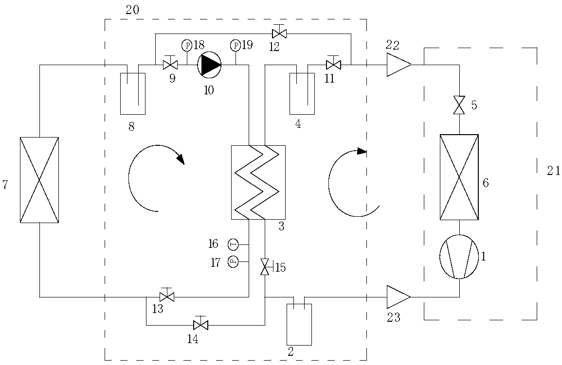
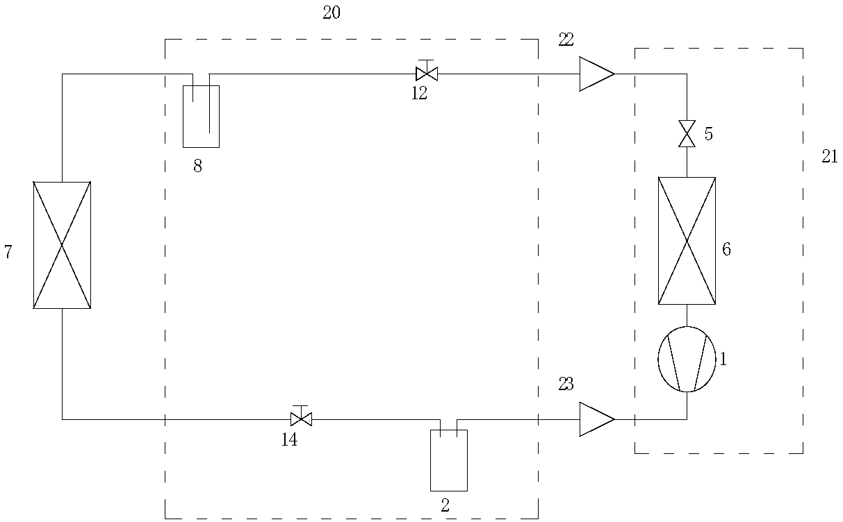
[0025] Such as figure 2 As shown, in the schematic block diagram of Embodiment 1 of an air conditioning unit joint adjustment tooling system of the present invention, it includes an indoor unit 21, an oil separator 2, a heat exchanger 3, a first liquid storage tank 4, a second liquid storage tank tank 8 , refrigerant pump 10 and condenser 7 , it can be understood that the indoor unit 21 includes a throttle valve 5 , an evaporator 6 and a compressor 1 .

[0026] It can be understood that the indoor unit 21, the oil separator 2, the heat exchanger 3, and the first liquid storage tank 4 are sequentially connected through pipelines to form an indoor circulation loop; the condenser 7, the second liquid storage tank 8, and the refrigerant pump 10 are connected through pipelines Connect in sequence to form an outdoor circulation loop. The indoor and outdoor circulation loops exchange heat through the heat exchanger 3, that is, the refrigerant pump 10 provides power for the outdoor ...


PUM


Abstract

The invention relates to an air conditioning unit joint debugging fixture system and a control method thereof. The system comprises an indoor unit (21), an oil separator (2), a heat exchanger (3), a first liquid storage tank (4), a second liquid storage tank (8), a refrigerant pump (10) and a condenser (7); the indoor unit (21), the oil separator (2), the heat exchanger (3) and the first liquid storage tank (4) are connected with one another sequentially through pipelines so as to form an indoor circulation loop; and the condenser (7), the second liquid storage tank (8), and the refrigerant pump (10) are connected with one another sequentially through pipelines so as to form an outdoor circulation loop. With the air conditioning unit joint debugging fixture system and the control method thereof of the invention adopted, indoor / outdoor independent operation modes and indoor / outdoor connection operation modes can be switched according to outdoor ambient temperature and indoor heat load demand, so that the return of the lubricating oil of a compressor during the debugging and testing operation process of an air-conditioner unit can be stabilized, and the stability and reliability of the air-conditioning unit which has been delivered out from a factory can be improved.

Description

technical field [0001] The invention relates to the field of testing of air-conditioning units, and more specifically relates to an air-conditioning unit joint debugging tooling system and a control method thereof. Background technique [0002] At present, after the indoor units are assembled in the air-conditioning production line, part or all of the units will be selected in the production joint debugging link, connected to the outdoor condenser and run for debugging, so as to identify possible operating risks and assembly problems of the indoor air-conditioning units. The joint debugging system currently used in the air-conditioning production line is as follows: figure 1 shown. [0003] figure 1 The application scheme of the joint debugging system shown will have the following problems: Since the debugging position of the indoor unit 21 is located in the production line, for large air-conditioning units, the supporting condenser 7 is relatively large in size. The requ...

Claims


Application Information

Patent Timeline
Patent Type & Authority Applications(China)
IPC IPC(8): G01M99/00
CPCG01M99/005G01M99/008Y02B30/70
Inventor 王颖曹会龙欧阳超波李垂君黄官飞
Owner SHENZHEN ITEAQ NETWORK POWER TECH CO LTD
Learn More