A manufacturing process of a four-way valve coil
A manufacturing process, four-way valve technology, applied in coil manufacturing, transformer/inductor coil/winding/connection, transformer/inductor components, etc. problems, to achieve stable service life, improve service life and improve efficiency.
- Summary
- Abstract
- Description
- Claims
- Application Information
AI Technical Summary
Problems solved by technology
Method used
Image
Examples
Embodiment 1
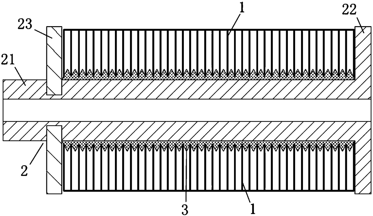
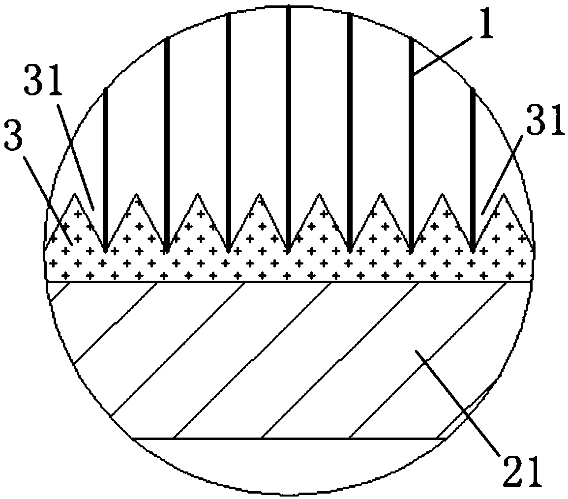
[0046] Firstly, an installation slot is provided on the wire rack body 21, and then an insulating resin layer 3 is provided on the outer surface of the wire rack body 21, and a limit position consistent with the number of coil turns of the coil winding 1 is set on the insulating resin layer 3. Grooves 31, the depth of each of the limiting grooves 31 is less than the distance between the tops of two adjacent limiting grooves 31, the insulating resin layer 3 is selected from phenolic resin, and on the insulating resin layer 3 Add glass fiber and silica nanoparticles with an average particle size of 70nm; then install the coil winding 1 on the wire frame body 21, and fix the second baffle 23 in the installation slot ; Check the appearance of the installed coil winding, and detect its coil resistance and inter-turn high voltage, and conduct a water immersion test and withstand voltage test; select a four-way valve coil with a qualified coil winding 1 for subsequent production.
Embodiment 2
[0048] Firstly, an installation slot is provided on the wire rack body 21, and then an insulating resin layer 3 is provided on the outer surface of the wire rack body 21, and a limit position consistent with the number of coil turns of the coil winding 1 is set on the insulating resin layer 3. Grooves 31, the depth of each of the limiting grooves 31 is less than the distance between the tops of two adjacent limiting grooves 31, the insulating resin layer 3 is epoxy resin, and the insulating resin layer Add asbestos fibers and silicon nitride nanoparticles with an average particle size of 80nm in 3; then install the coil winding 1 on the wire frame body 21, and fix the second baffle plate 23 in the installation slot Inside; check the appearance of the installed coil winding, and detect its coil resistance and inter-turn high voltage, as well as conduct a water immersion test and withstand voltage test; select a four-way valve coil with a qualified coil winding 1 for subsequent p...
Embodiment 3
[0050] Firstly, an installation slot is provided on the wire rack body 21, and then an insulating resin layer 3 is provided on the outer surface of the wire rack body 21, and a limit position consistent with the number of coil turns of the coil winding 1 is set on the insulating resin layer 3. Grooves 31, the depth of each of the limiting grooves 31 is less than the distance between the tops of two adjacent limiting grooves 31, the insulating resin layer 3 is epoxy resin, and the insulating resin layer Add asbestos fibers and silica nanoparticles with an average particle size of 90nm in 3; then install the coil winding 1 on the wire frame body 21, and fix the second baffle plate 23 in the installation slot Inside; check the appearance of the installed coil winding, and detect its coil resistance and inter-turn high voltage, as well as conduct a water immersion test and withstand voltage test; select a four-way valve coil with a qualified coil winding 1 for subsequent production...
PUM
| Property | Measurement | Unit |
|---|---|---|
| The average particle size | aaaaa | aaaaa |
| The average particle size | aaaaa | aaaaa |
| The average particle size | aaaaa | aaaaa |
Abstract
Description
Claims
Application Information
 - R&D
- Intellectual Property
- Life Sciences
- Materials
- Tech Scout
- Unparalleled Data Quality
- Higher Quality Content
- 60% Fewer Hallucinations
Browse by: Latest US Patents, China's latest patents, Technical Efficacy Thesaurus, Application Domain, Technology Topic, Popular Technical Reports.
© 2025 PatSnap. All rights reserved.Legal|Privacy policy|Modern Slavery Act Transparency Statement|Sitemap|About US| Contact US: help@patsnap.com


