
Multi-tangential-flow drum corn threshing and cleaning device
The technology of a corn threshing and cleaning device is applied in the field of agricultural machinery, which can solve the problems of high labor intensity, high cost, and many corn harvesting operations, and achieve the effects of reducing operation links, improving efficiency and compact structure.
- Summary
- Abstract
- Description
- Claims
- Application Information
AI Technical Summary
Problems solved by technology
Method used
Image

Examples
Embodiment Construction
[0069] The present invention will be further described below in conjunction with the accompanying drawings and embodiments.
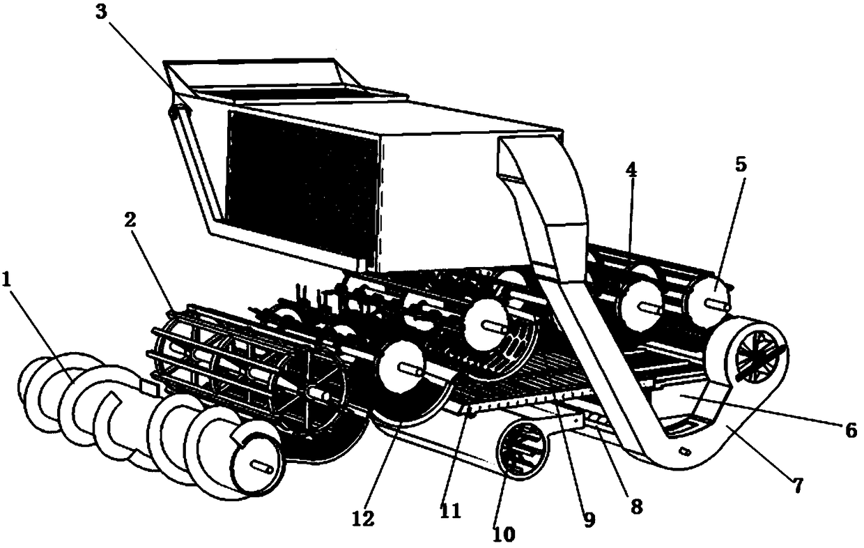
[0070] Such as figure 1 As shown, a multi-cut flow drum corn threshing and cleaning device includes a cutting unit, a threshing unit, a cleaning unit and a collecting unit.
[0071] The cutting unit includes an auger 1 .
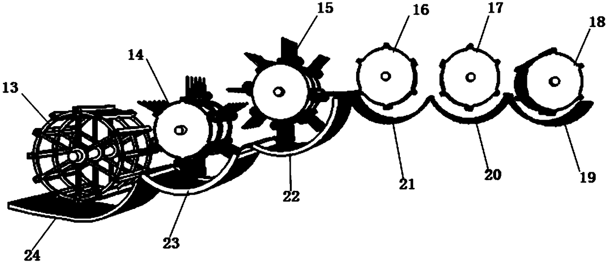
[0072] The threshing unit includes a pressure feeding device 2 , a finger-type feeding device 12 , an initial removal device 9 , a main removal device 4 and a re-extraction device 5 arranged in sequence from front to back.
[0073] The pressure feeding device 2 is arranged at the rear of the auger 1 .
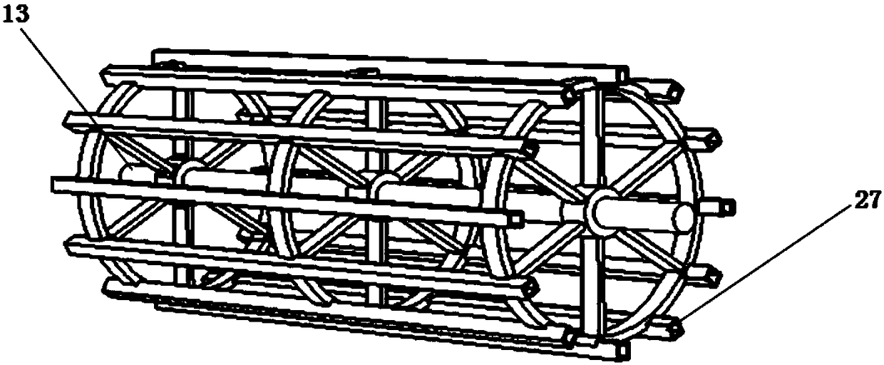
[0074] Such as figure 2 and image 3 As shown, the pressure-feeding device 2 includes a pressure-feeding roller 13 and a pressure-feeding concave plate 24 arranged under the pressure-feeding roller 13 .
[0075] The outer surface of the pinch roller 13 is uniformly distributed with a plurality of pinch strips 27 parallel to the r...
PUM
 Abstract
Description
Claims
Application Information