Novel automatic sock takeoff device

An automatic sock removal device and a new type of technology, applied in clothing, applications, hangers, etc., can solve the problems of difficulty in uniform customization, easy to be worn, and troublesome use of automatic socks removal shoes and their devices.

Inactive Publication Date: 2018-06-22
宋彦震
View PDF0 Cites 0 Cited by
  • Summary
  • Abstract
  • Description
  • Claims
  • Application Information

AI Technical Summary

Problems solved by technology

[0009] The above-mentioned patents have the following disadvantages. First, the legs are easily scratched or pinched during the upward movement of the legs, which poses a certain potential safety hazard.
Second, the legs may not be caught by the sock clamp or the auxiliary pins during the ascent, and the sock removal fails. There is a great possibility of failure and repeated operations are required.
Third, the thickness of the legs of people of different weights is different, and there are great individual differences, so it is difficult to unify the specifications and standards of products
[0013] The invention patent "automatically attracting socks and taking off magnetic shoes" has the following disadvantages. First, designing a hole at the heel inside the shoe or the front end of the shoe has a certain impact on the stability of the shoe. The hole at the heel makes the height of the sole part Reduced, easy to be stepped on, deformed and broken
Second, the first magnetic steel is fixed on the heel of the sock or the front end of the sock. The heel and the front end of the sock are the most likely to be worn out. It is easy to be torn due to large deformation. The part where the first magnet is fixed needs special reinforcement. It is not suitable for existing socks on the market, and it is difficult to uniformly customize them.
[0015] The invention patent "automatic sock-off shoes and its device" has the following disadvantages. First, the automatic sock-off shoes and its device are cumbersome to use. Every time you use it, you must align the mouth-type buckle with the L-shaped hook on the top of the rear end of the shoe, and then If it is set on the top, sometimes there will be deviations in the inaccuracy, which requires multiple operations, and the efficiency is relatively low
[0016] Second, the mouth-type buckle in the invention patent "Automatic Sock-Removing Shoes and Its Device" sometimes breaks away from the L-shaped hook due to human movement, and the socks cannot be taken off at the same time when taking off the shoes
[0017] Thirdly, due to the connection by nesting together, there must be a certain gap between the mouth buckle and the L-shaped hook on the top of the rear end of the shoe. When walking, the mouth buckle will collide with the L-shaped hook and make noise
[0018] Fourth, in the invention patent "Automatic Sock-Removing Shoes and Its Device", the connecting strip and mouth-type buckle are always connected and fixed with the socks. When the socks need to be cleaned, the socks cannot be separated from the buckle. Mechanical damage to the clasp when washing socks
[0019] Fifth, in winter, for some people who want to wear socks when wearing slippers at home, and do not want the socks to be taken off with the shoes when changing slippers, it is unsatisfactory. When using it, the mouth-type buckle should be placed on the top of the back end of the shoes every time. On the L-shaped hook of the shoes, the mouth buckle must be removed from the L-shaped hook every time when it is taken off, which increases the trouble of use. If the mouth buckle is not set on the L-shaped hook at the top of the rear end of the shoe, the mouth The buckle will swing greatly with the movement of the person and collide with the shoe

Method used


Image

  • Novel automatic sock takeoff device
  • Novel automatic sock takeoff device
  • Novel automatic sock takeoff device

Examples


no. 1 example

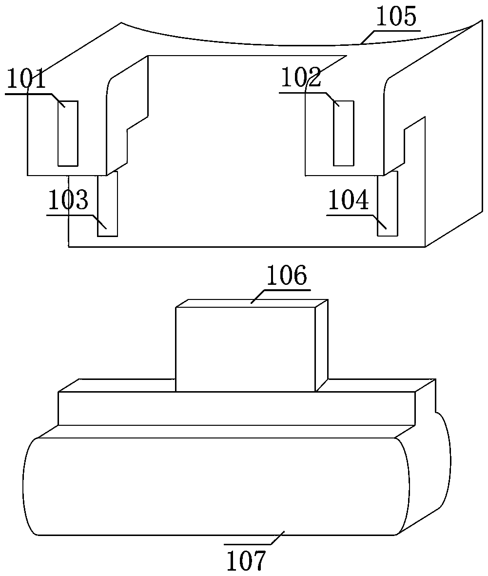
[0066] figure 1 and figure 2 Among them, there are two grooves on the 105 fixed block, the shape of the groove is complementary to the shape of the 107 buckle, and the contact surface between the groove and the 107 buckle is a right-angled surface.

[0067] There are four magnets on the 105 fixed block, respectively 101 first magnets, 102 second magnets, 103 third magnets and 104 fourth magnets, 101 first magnets and 102 second magnets are fixed on 105 Above the fixed block, 101 the first magnetic steel and 102 the second magnetic steel are used to tightly attract the 107 buckle above the 105 fixed block; 103 the third magnetic steel and 104 the fourth magnetic steel are fixed below the 105 fixed block , inside the groove, the 103 third magnetic steel and the 104 fourth magnetic steel are used to tightly attract the 107 buckle under the 105 fixing block, so that the 107 buckle is tightly fixed in the groove.

[0068] There are two magnetic steels on the 107 buckle, the posi...

no. 2 example

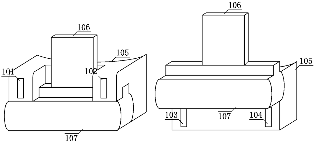
[0071] image 3 and Figure 4 Among them, there are two grooves on the 105 fixed block, the shape of the groove is complementary to the shape of the 107 buckle, and the contact surface between the groove and the 107 buckle is an acute angle surface.

[0072] There are four magnets on the 105 fixed block, respectively 101 first magnets, 102 second magnets, 103 third magnets and 104 fourth magnets, 101 first magnets and 102 second magnets are fixed on 105 Above the fixed block, 101 the first magnetic steel and 102 the second magnetic steel are used to tightly attract the 107 buckle above the 105 fixed block; 103 the third magnetic steel and 104 the fourth magnetic steel are fixed below the 105 fixed block , inside the groove, the 103 third magnetic steel and the 104 fourth magnetic steel are used to tightly attract the 107 buckle under the 105 fixing block, so that the 107 buckle is tightly fixed in the groove.

no. 3 example

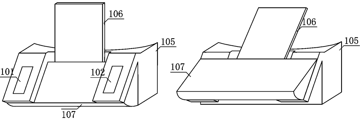
[0074] Figure 5 and Figure 6 Among them, there are four grooves on the 105 fixing block, the shape of the grooves is complementary to that of the 107 buckle, and the contact surface between the grooves and the 107 buckle is a cylindrical surface, which effectively reduces the thickness and volume of the 105 fixing block.

[0075] There are four magnets on the 105 fixed block, respectively 101 first magnets, 102 second magnets, 103 third magnets and 104 fourth magnets, 101 first magnets and 102 second magnets are fixed on 105 Above the fixed block, 101 the first magnetic steel and 102 the second magnetic steel are used to tightly attract the 107 buckle in the groove above the fixed block 105; 103 the third magnetic steel and 104 the fourth magnetic steel are fixed at 105 Below the block, next to the groove, 103 third magnetic steels and 104 fourth magnetic steels are used to closely attract the 107 buckles below the 105 fixed block, so that the 107 buckles are tightly fixed ...


PUM


Abstract

A novel automatic sock takeoff device comprises first magnetic steel, second magnetic steel, third magnetic steel, fourth magnetic steel, fixing blocks, buckles, first connection long strips, second connection long strips and socks. Whether to take off the socks along with shoes or not during slipper changing is determined by selecting to put the buckles above or below the fixing blocks. When thebuckles are clamped on grooves below the fixing blocks, the socks are automatically taken off when the shoes are taken off; when the buckles are adsorbed above the fixing blocks, the socks do not taken off along with the shoes. In the process of taking off the shoes, when feet are pulled out of the shoes, the second connection long strips pull welts at heels, tension on the socks generated by thesecond connection long strips is much larger than friction force between the feet and the socks, after the feet are pulled out of the shoes, the socks are taken off from the feet naturally. The novelautomatic sock takeoff device is simple in structure and convenient to use; trouble of flushing hands with water after sock takeoff and water waste are avoided, and the socks which are taken off are still connected with the shoes, so that leaving about of the socks is avoided, and convenience is brought to management.

Description

technical field [0001] The invention relates to the technical field of auxiliary devices for daily necessities, in particular to a novel automatic sock removal device. Background technique [0002] For most people, wearing socks while wearing slippers indoors will cause some discomfort, and people often choose to go barefoot. Taking off socks after taking off shoes has become the habit of many people. Because socks are relatively dirty, washing hands after taking off socks by hand is bothersome and wastes water resources. [0003] For some elderly people who have difficulty walking and people with lumbar diseases, it is not easy to bend over and lift their feet, and even accidents may occur. Taking off socks adds a certain burden and trouble to life. [0004] There are some assisting devices for taking off socks in the prior art, and these assisting devices for removing socks are mainly aimed at elderly people who are inconvenient to walk and people with lumbar diseases. ...

Claims


Application Information

Patent Timeline
Patent Type & Authority Applications(China)
IPC IPC(8): A47G25/90
CPCA47G25/908
Inventor 宋彦震
Owner 宋彦震
Why Eureka
Try Eureka