Stamping die with automatic material lifting function

A stamping die, automatic technology, applied in metal processing equipment, peeling devices, forming tools, etc., can solve the problems of difficult preparation, difficult to take out sheet workpieces, and complex automatic starting structure, so as to reduce labor workload and improve The effect of production efficiency

Inactive Publication Date: 2018-06-22
SUZHOU RIPU MOLD CO LTD
View PDF6 Cites 0 Cited by
  • Summary
  • Abstract
  • Description
  • Claims
  • Application Information

AI Technical Summary

Problems solved by technology

[0003] The technical problem mainly solved by the present invention is to provide a stamping die that can automatically lift materials, which solves the problems that sheet-shaped workpieces are difficult to take out on the stamping die, and the automatic material lifting structure is complicated and difficult to prepare.

Method used


Image

  • Stamping die with automatic material lifting function

Examples


Embodiment Construction

[0010] The preferred embodiments of the present invention will be described in detail below in conjunction with the accompanying drawings, so that the advantages and features of the present invention can be more easily understood by those skilled in the art, so as to define the protection scope of the present invention more clearly.

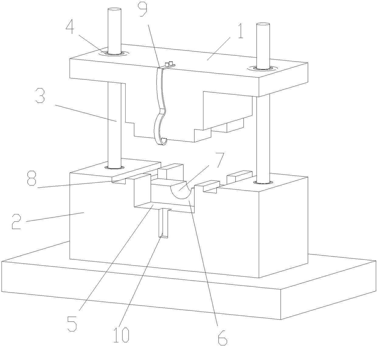
[0011] Please refer to the attached figure 1 , the embodiment of the present invention includes:

[0012] A stamping die capable of automatic material lifting, comprising an upper die 1, a lower die 2 and a guide post 3. The lower die 2 is provided with a mounting hole; the mounting hole is provided with a guide post 3 for the lifting and guiding of the upper die 1, and the upper die 1 is provided with a guide sleeve 4 matching the guide post 3, and the upper die 1 is matched with the guide post 3 through the guide sleeve . Two guide pillars 3 are provided, and the two guide pillars 3 are fitted on the upper mold 1 through the guide sleeve 4 . ...


PUM


Abstract

The invention discloses a stamping die with an automatic material lifting function. The stamping die comprises an upper die body, a lower die body and a guiding column. A mounting hole is formed in the lower die body and internally provided with a guiding column for lifting guiding of the upper die body, and a guiding sleeve matched with the guiding column is arranged on the upper die body. The upper die body is matched with the guiding column through the guiding sleeve, a machining area for stamping forming is arranged on the lower die body and penetrates in the width direction of the lower die body, and a protruding positioning block is arranged in the center of the machining area. A circular-arc-shaped positioning groove is formed in the positioning block, and grooves for positioning the upper die body are further formed in the end faces of the two sides in the length direction of the machining area. An arc-shaped hook plate for material lifting is further arranged on the upper diebody and fixed to the end face of one side of the upper die body, and the lower end of the arc-shaped hook plate is a hooking-up end. The hooking-up end is lower than the bottom face of the upper diebody, an arc-shaped area with the function of recovering deformation towards the die is arranged on the arc-shaped hook plate, and the hooking-up end is a circular arc upwards bending towards the die.A straight groove matched with the arc-shaped hook plate is formed in the side face of the lower die body and leads to the bottom face in the machining area.

Description

technical field [0001] The invention relates to the field of mold structure, in particular to a stamping mold capable of automatic material lifting. Background technique [0002] At present, in the process of cold stamping blanking on the stamping die, since the general blanking is blanking without waste around, the material is usually returned by the action of the unloading plate on the lower die, so that the edge of the material can lift the blank Remove from the lower mold, and then manually shake the steel plate to collect the blanks. This purely manual picking method is time-consuming, labor-intensive, and the production cycle is slow. In addition, if the production method of cutting off the edge of the material as waste is punched, it will bring a lot of inconvenience to take the material. Contents of the invention [0003] The technical problem mainly solved by the present invention is to provide a punching die capable of automatic lifting, which solves the problem...

Claims


Application Information

Patent Timeline
IPC IPC(8): B21D37/10B21D45/08
CPCB21D37/10B21D45/08
Inventor 刘曾
Owner SUZHOU RIPU MOLD CO LTD
Why Eureka
Try Eureka