Crank connecting rod type ball net drawing device

A technology of crank connecting rod and ball collecting net is applied in the directions of cleaning heat transfer devices, non-rotating equipment cleaning, lighting and heating equipment, etc. Function and quality issues, to achieve the effect of high rigidity and strength, easy processing and assembly, function and quality assurance

Inactive Publication Date: 2008-03-12
上海丰庆机电设备工程有限公司
View PDF7 Cites 3 Cited by
  • Summary
  • Abstract
  • Description
  • Claims
  • Application Information

AI Technical Summary

Problems solved by technology

But the crank-link mechanism in this net receiving device is assembly type, has two crank axle shafts in its structure, is equipped with respectively crank respectively, is provided with common crank in the middle and is connected to two crank separately by crank pin Together, in this way, concentric installation is required, resulting in very high machining accuracy and assembly accuracy, which increases the difficulty and cost of production. In the assembly process, repeated disassembly and assembly and multiple adjustments are required to meet the requirements. The installation operation is troublesome, and assembly The rigidity and strength of the conventional structure are poor, and it is difficult to guarantee the function and quality

Method used


Image

  • Crank connecting rod type ball net drawing device
  • Crank connecting rod type ball net drawing device
  • Crank connecting rod type ball net drawing device

Examples


Embodiment Construction

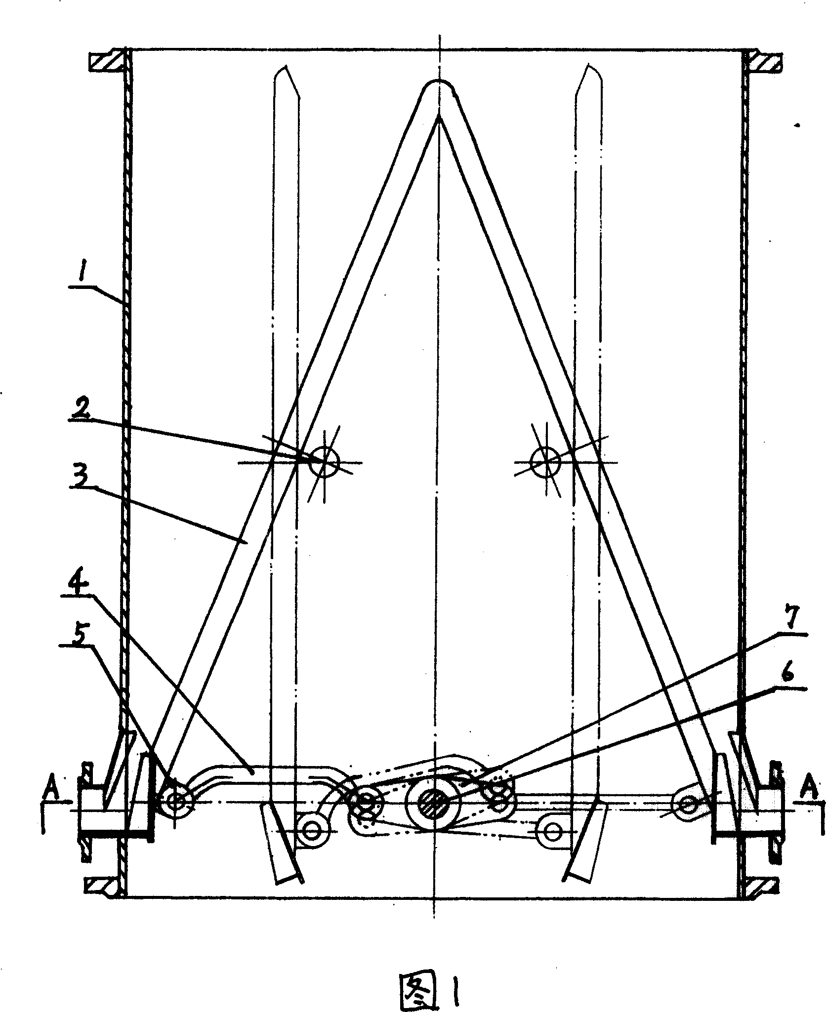
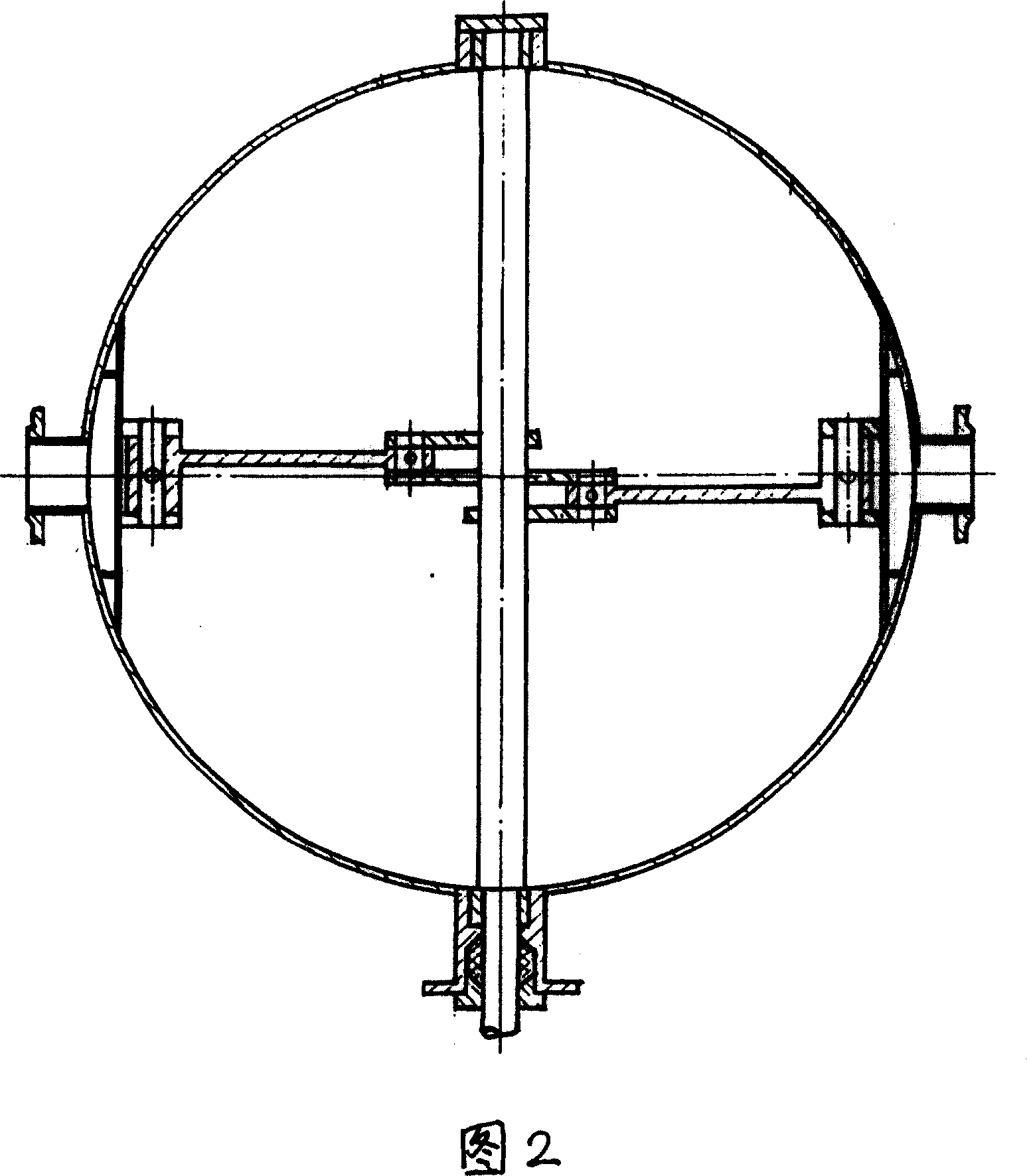
[0021] As shown in Figures 1 and 2, the crank-link type ball net collection device according to the present invention has a double net plate structure, including a ball collection cylinder 1, a net plate 3, a net plate rotating shaft 2, a rubber ball outlet pipe, and a flow guide. plate, transmission, executive device and control device, the rotating shaft 2 of the screen plate is placed on the cylinder 1, the lower part of the screen plate 3 is provided with a swing support 5, and the execution device is a crank-link mechanism, and the swing support 5 is connected to the actuator The connecting rod 4 of the device is hinged, the other end of the connecting rod 4 is hinged with the crank 7, and the crank shaft 6 of the transmission device is connected with the operating device outside the ball receiving tube, and the crank shaft 6 is the crank through shaft arranged on the ball receiving tube 1 , the shape of the connecting rod 4 adapts to the swing angle of the crank 7, and th...


PUM


Abstract

This invention relates to a winch connection lever collection net, which comprises the ball collection cylinder, net plate, net plate rotation axis, rubber ball draw-off pipe, flow guiding plate, driving and executive devices and operation devices. The axis is located on the cylinder and the net plate down part is located with a swing rack. The executive device is the winch connection lever structure and the rotation rack and the executive device connection lever are hinged with one end connected to the winch lever. The driving device winch axis is connected to the operation device outside the ball collection cylinder with its winch located on the axis of the cylinder.

Description

technical field [0001] The invention relates to a crank-and-rod ball collecting net device for continuously cleaning condensers with rubber balls, which is used for recycling rubber balls for continuous cleaning of cooling water pipes of condensers of thermal power or nuclear power units and various surface heat exchangers. Background technique [0002] It is an effective method commonly used in thermal power units to continuously and automatically clean the pollution of the cooling water pipe of the condenser with a single rubber ball. For the rubber ball cleaning device that can be put into use, only normal operation and maintenance are required to reduce the end difference of the condenser. The purpose of improving vacuum, saving fuel and increasing efficiency. [0003] The key device in the rubber ball cleaning system is the ball collecting net device, which has been improved many times so far. The patent No. ZL01268792.8 designed by the applicant is that the ball collec...

Claims


Application Information

Patent Timeline
Patent Type & Authority Patents(China)
IPC IPC(8): F28G1/12
Inventor 王永杰王鸿博王鸿宇
Owner 上海丰庆机电设备工程有限公司
Why Eureka
Try Eureka