Stand column

A column and body technology, applied in the field of machine tool parts, can solve the problems that affect the machining accuracy of workpieces and product quality, cannot meet the requirements of high-efficiency load cutting, and the machine tool is not tightly and firmly combined, so as to improve machining accuracy and product quality. , to meet the effect of high-efficiency load cutting and the overall compact structure of the column

Inactive Publication Date: 2018-06-22
安徽金义得机械有限公司
View PDF8 Cites 5 Cited by
  • Summary
  • Abstract
  • Description
  • Claims
  • Application Information

AI Technical Summary

Problems solved by technology

[0003] (1) It is heavy and thick, inconvenient to install, the amount of steel used is large, the production cost is high, and the strength and rigidity cannot be guaranteed, and it cannot meet the requirements of high-efficiency load cutting, and cannot meet the requirements of energy conservation and environmental protection;
[0004] (2) The combination of the base and the column of the machine tool is not tight and firm enough, which makes the machine tool not stable enough during operation. Due to factors such as vibration of the machine tool during processing, it directly affects the machining accuracy of the workpiece and the quality of the product;
[0005] (3) The center of gravity of the column is high, which is not conducive to stability

Method used


Image

  • Stand column
  • Stand column

Examples


Embodiment Construction

[0028] In order to have a further understanding and recognition of the structural features and the achieved effects of the present invention, the preferred embodiments and accompanying drawings are used for detailed description, as follows:

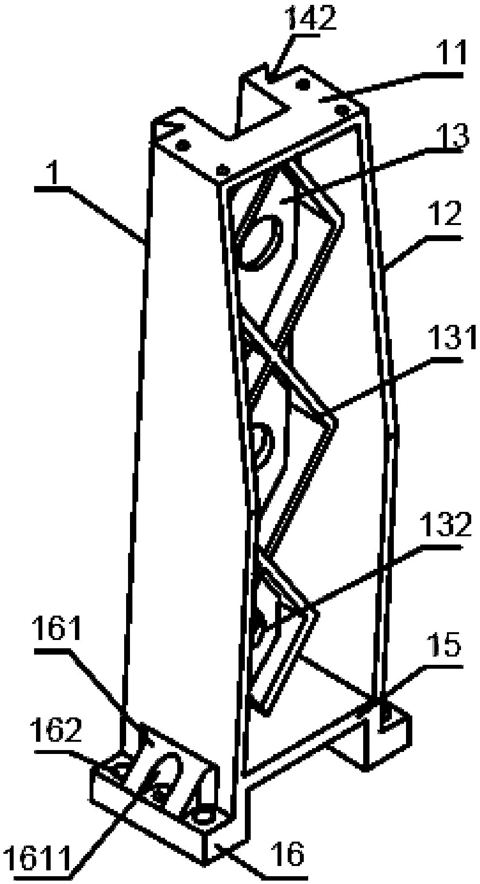
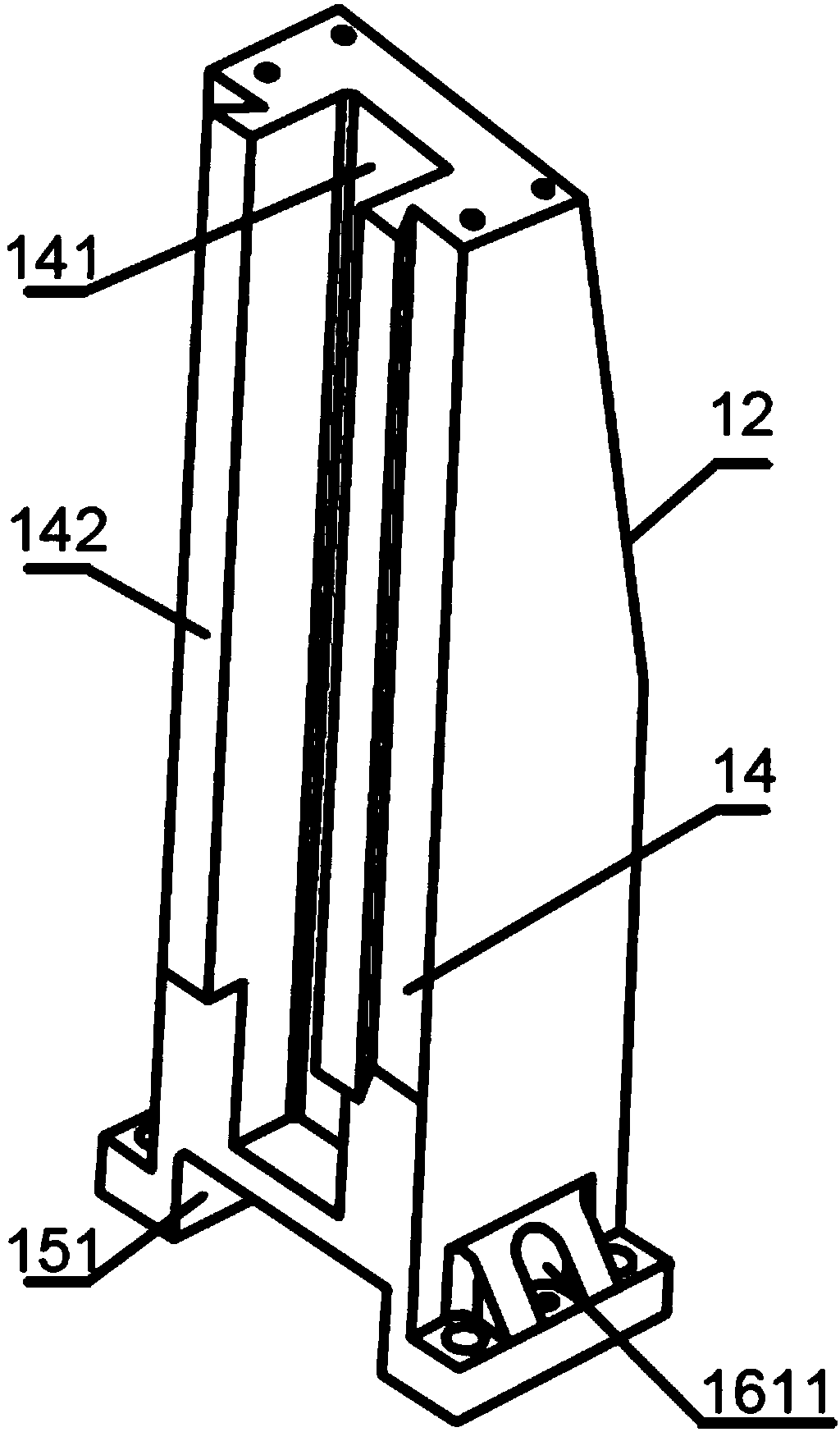
[0029] Such as figure 1 , figure 2 As shown, the column includes a column body 1, and the column body 1 includes a connection surface 13. The connection surface 13 extends vertically from the top surface 11 of the column body 1 to the bottom surface 15, and the connection surface 13 separates the column body 1 into a front cavity and a back cavity. 141, the connecting surface 13 is provided with a hoisting hole 132;

[0030] There are multiple connecting surface reinforcing ribs 131 arranged on the connecting surface 13 in the front cavity, and the connecting surface reinforcing ribs 131 connect the left side wall and the right side wall of the column body 1, and connect the top surface 11 and the bottom surface 15 of the column body 1 ...


PUM


Abstract

The invention provides a stand column. The stand column comprises a stand column body, wherein the stand column body comprises a connecting surface; the connecting surface perpendicularly extends to the bottom surface from the top surface of the stand column body, and divides the stand column body into a front cavity and a back cavity; hoisting holes are formed in the connecting surface; a plurality of connecting surface reinforcing ribs which are arranged on the connecting surface are arranged in the front cavity, are connected with the left side wall and the right side wall of the stand column body, and are connected to the top surface and the bottom surface of the stand column body; the connecting surface reinforcing ribs and the hoisting holes are staggered; the back cavity does not have a top surface; mounting slide tracks are integrally formed on the back of the back cavity, are symmetrically arranged on two sides of the outside of the back cavity, and downwards extend to the position above the bottom surface from the top surface of the stand column; supports are arranged on the lower portion of the stand column body, extend to two sides from the position below the bottom surface and are symmetrically distributed, so that a bottom groove is formed below the bottom surface; and mounting holes are formed in each support. The stand column is low in cost and high in strength,and is firmly and stably combined to a base of a machine tool.

Description

technical field [0001] The invention relates to the technical field of machine tool parts, in particular to a column. Background technique [0002] The column is one of the important parts on the machine tool, however, the existing machine column has the following deficiencies: [0003] (1) It is heavy and thick, inconvenient to install, the amount of steel used is large, the production cost is high, and the strength and rigidity cannot be guaranteed, and it cannot meet the requirements of high-efficiency load cutting, and cannot meet the requirements of energy conservation and environmental protection; [0004] (2) The combination of the base and the column of the machine tool is not tight and firm enough, which makes the machine tool not stable enough during operation. Due to factors such as vibration of the machine tool during processing, it directly affects the machining accuracy of the workpiece and the quality of the product; [0005] (3) The center of gravity of the ...

Claims


Application Information

Patent Timeline
Patent Type & Authority Applications(China)
IPC IPC(8): B23Q1/01
CPCB23Q1/015
Inventor 杨有才
Owner 安徽金义得机械有限公司
Why Eureka
Try Eureka