
Numerically-controlled machine tool waste collecting device

A waste collection, CNC machine tool technology, applied in metal processing machinery parts, maintenance and safety accessories, metal processing equipment, etc., can solve the problems of cutting fluid use, insufficient machine tools, cutting droplets falling on the ground, etc.

Inactive Publication Date: 2018-06-22
欧振云
View PDF7 Cites 5 Cited by
  • Summary
  • Abstract
  • Description
  • Claims
  • Application Information

AI Technical Summary

Problems solved by technology

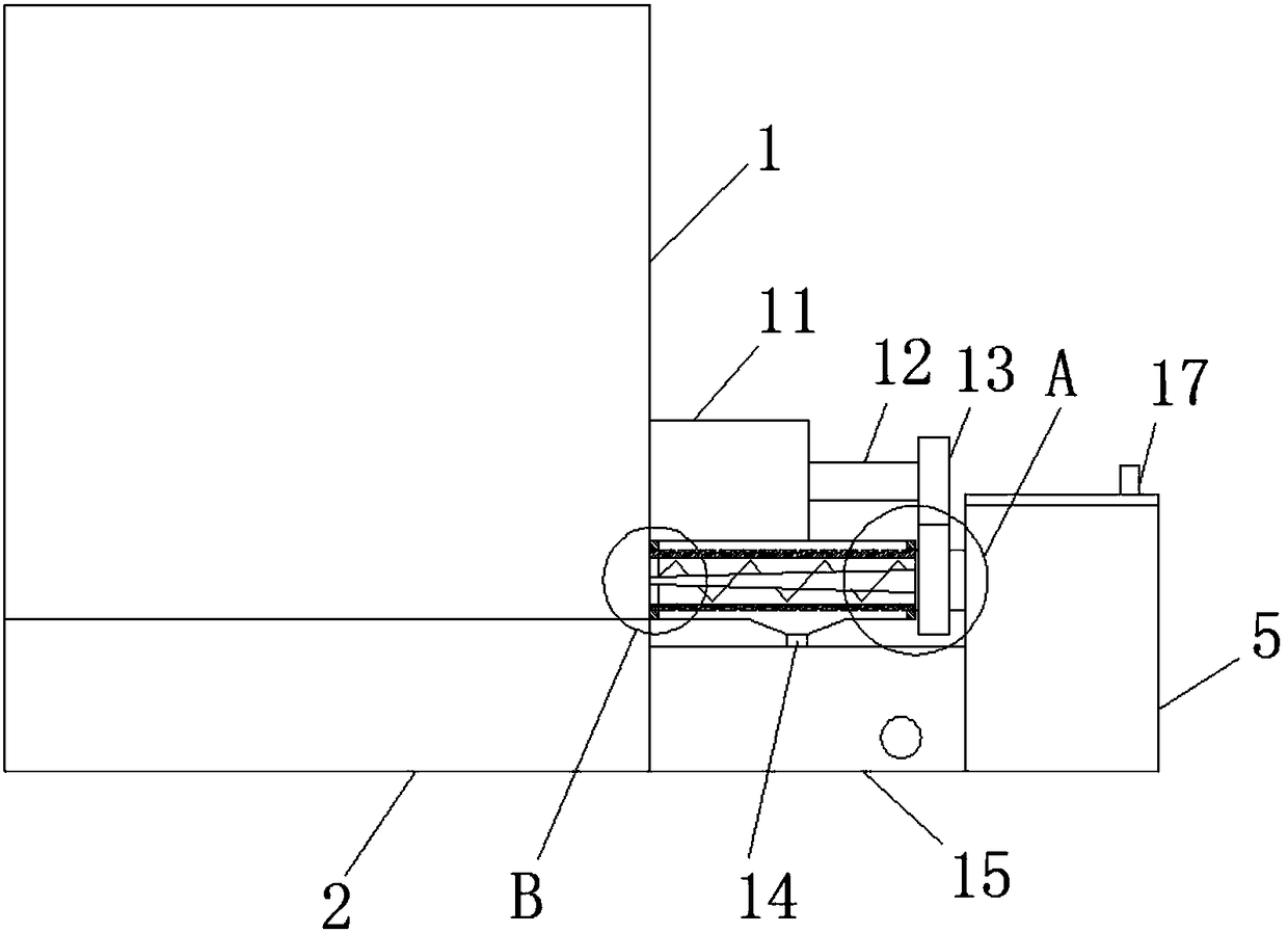
[0004] The purpose of the present invention is to solve the problem in the prior art that the chips will retain the cutting fluid, causing the machine tool to use without enough cutting fluid, and at the same time, the cutting fluid will drop on the ground when cleaning the chips, and propose a waste collection device for CNC machine tools

Method used


Image

  • Numerically-controlled machine tool waste collecting device
  • Numerically-controlled machine tool waste collecting device
  • Numerically-controlled machine tool waste collecting device

Examples


Embodiment Construction

[0020] The following will clearly and completely describe the technical solutions in the embodiments of the present invention with reference to the accompanying drawings in the embodiments of the present invention. Obviously, the described embodiments are only some, not all, embodiments of the present invention.

[0021] In describing the present invention, it should be understood that the terms "upper", "lower", "front", "rear", "left", "right", "top", "bottom", "inner", " The orientation or positional relationship indicated by "outside", etc. is based on the orientation or positional relationship shown in the drawings, and is only for the convenience of describing the present invention and simplifying the description, rather than indicating or implying that the referred device or element must have a specific orientation, so as to Specific orientation configurations and operations, therefore, are not to be construed as limitations on the invention.

[0022] refer to Figure ...


PUM


Abstract

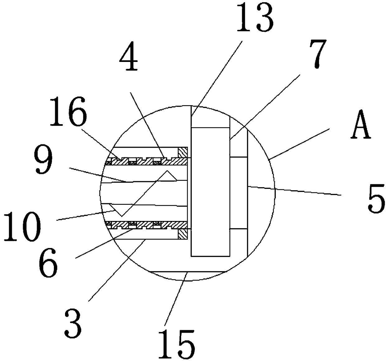
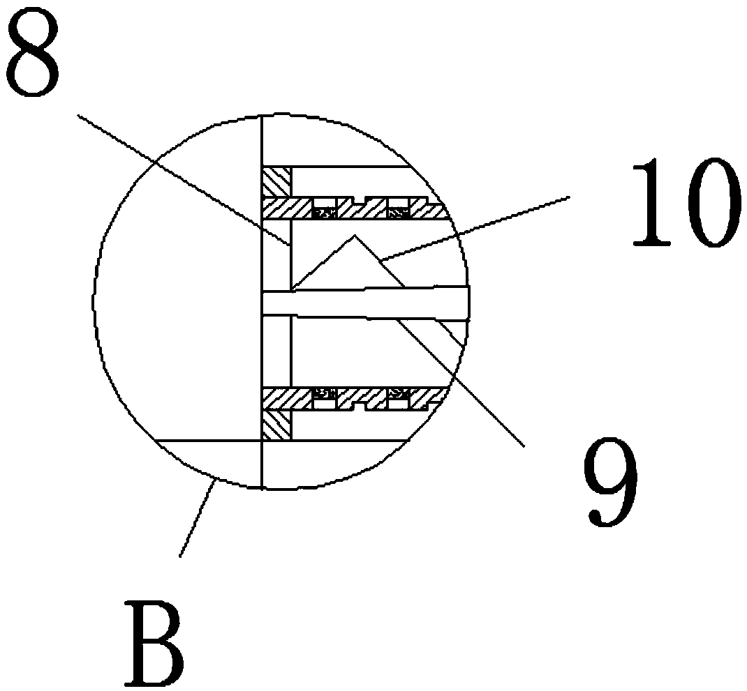
The invention discloses a numerically-controlled machine tool waste collecting device. The numerically-controlled machine tool waste collecting device comprises a machine tool body, the lower surfaceof the machine tool body is fixedly connected with a base, one side of the machine tool body is fixedly communicated with a first drainage pipe, and the inside of the first drainage pipe is fixedly connected with two bearings which are arranged at both ends of the first drainage pipe; a discharge pipe is rotatingly connected simultaneously inside the two bearings, one end of the discharge pipe iscommunicated with the inside of the machine tool body, the other end of the discharge pipe extends out of the first drainage pipe and is communicated with a waste tank, the discharge pipe is rotatingly connected to the waste tank through the bearings, the outer wall of one side of the discharge pipe, which extends into the first drainage pipe, is provided with a plurality of uniformly-distributeddehydrating holes, and filter screens are fixedly connected inside very dehydrating hole. The numerically-controlled machine tool waste collecting device is simple in structure, convenient to operateand capable of separating cuttings and cutting fluid, preventing a large amount of the cutting liquid inside the machine tool from being retained inside the cuttings as well as from dropping onto theground when the cuttings are cleaned.

Description

technical field [0001] The invention relates to the technical field of numerical control machine tools, in particular to a waste collection device for numerical control machine tools. Background technique [0002] CNC machine tool is the abbreviation of numerical control machine tool, which is an automatic machine tool equipped with a program control system. The control system can logically process programs with control codes or other symbolic instructions, decode them, express them in coded numbers, and input them into the numerical control device through the information carrier. After calculation and processing, various control signals are sent by the CNC device to control the movement of the machine tool, and the parts are automatically processed according to the shape and size required by the drawing. The CNC machine tool will produce waste such as chips during the processing. [0003] When CNC machine tools process metal workpieces, cutting fluid or cutting oil is gene...

Claims


Application Information

Patent Timeline
IPC IPC(8): B23Q11/00B23Q11/10
CPCB23Q11/0042B23Q11/1069
Inventor 欧振云
Owner 欧振云
Learn More