Embroidery machine head and embroidery machine

An embroidery machine and machine head technology, applied in the field of embroidery machines, can solve the problems of increasing the difficulty of assembling the machine head, increasing the production cost of the machine head, inconvenient maintenance and replacement, etc., to achieve rich functional uses, meet market demands, and reduce assembly. time consuming effect

Pending Publication Date: 2018-06-22
ZHEJIANG XINSHENG SEWING EQUIP
View PDF8 Cites 9 Cited by
  • Summary
  • Abstract
  • Description
  • Claims
  • Application Information

AI Technical Summary

Problems solved by technology

When engraving holes in this way, the electromagnet needs to be turned on normally through the electric control device. Because the frequency of the needle bar driver’s back and forth movement is relatively high, the electromagnet is easily damaged after working for a period of time.
In addition, since the electromagnet is generally installed inside the machine head, it is not convenient for maintenance and replacement.
Furthermore, in order to realize the driving of the electromagnet to the needle bar driver, it is necessary to add necessary transmission parts between the electromagnet and the needle bar driver. Since the internal space of the machine head is very small, it will increase the difficulty of assembling the machine head. Will increase the production cost of the head

Method used


Image

  • Embroidery machine head and embroidery machine
  • Embroidery machine head and embroidery machine
  • Embroidery machine head and embroidery machine

Examples


Embodiment 1

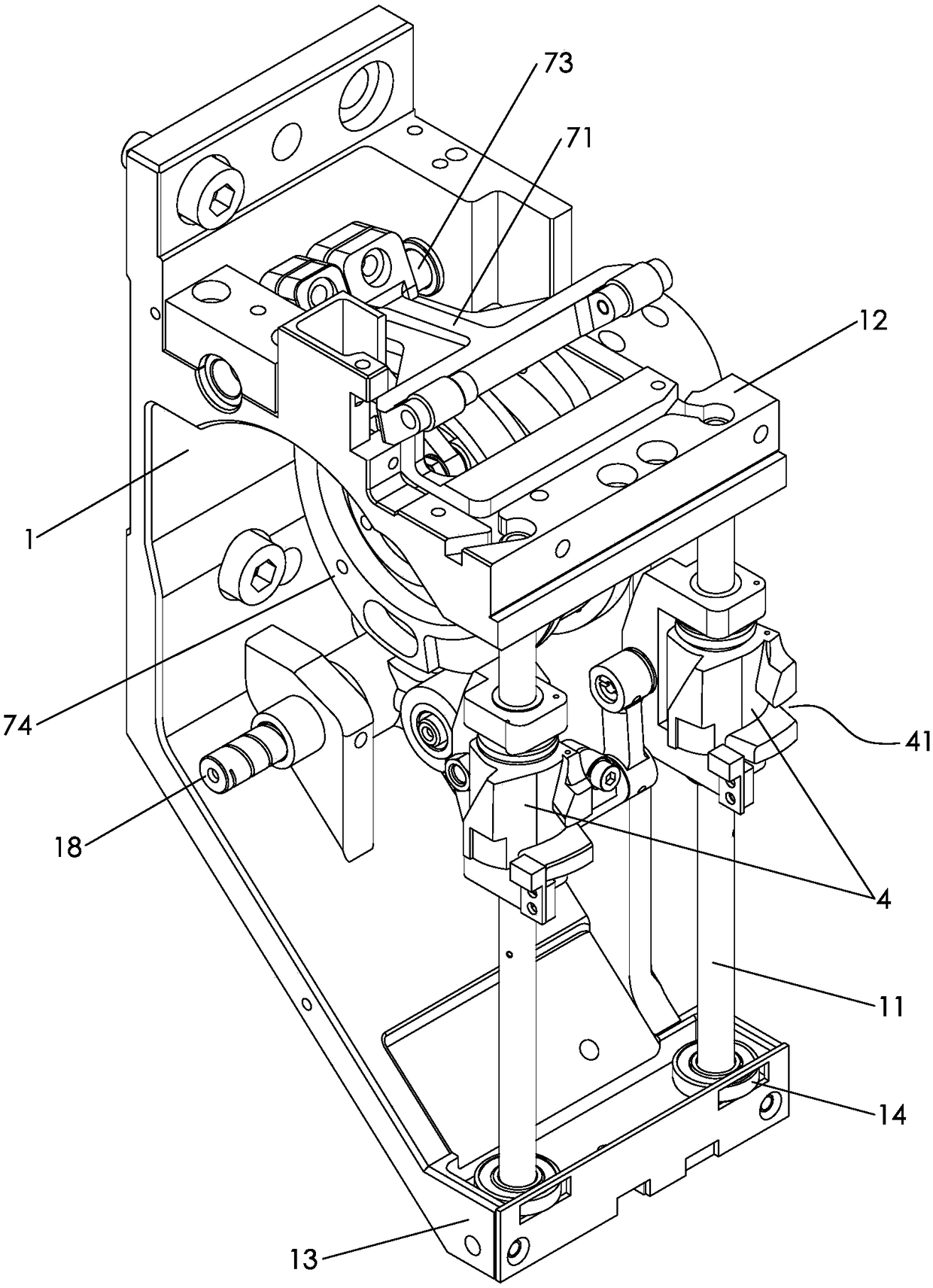
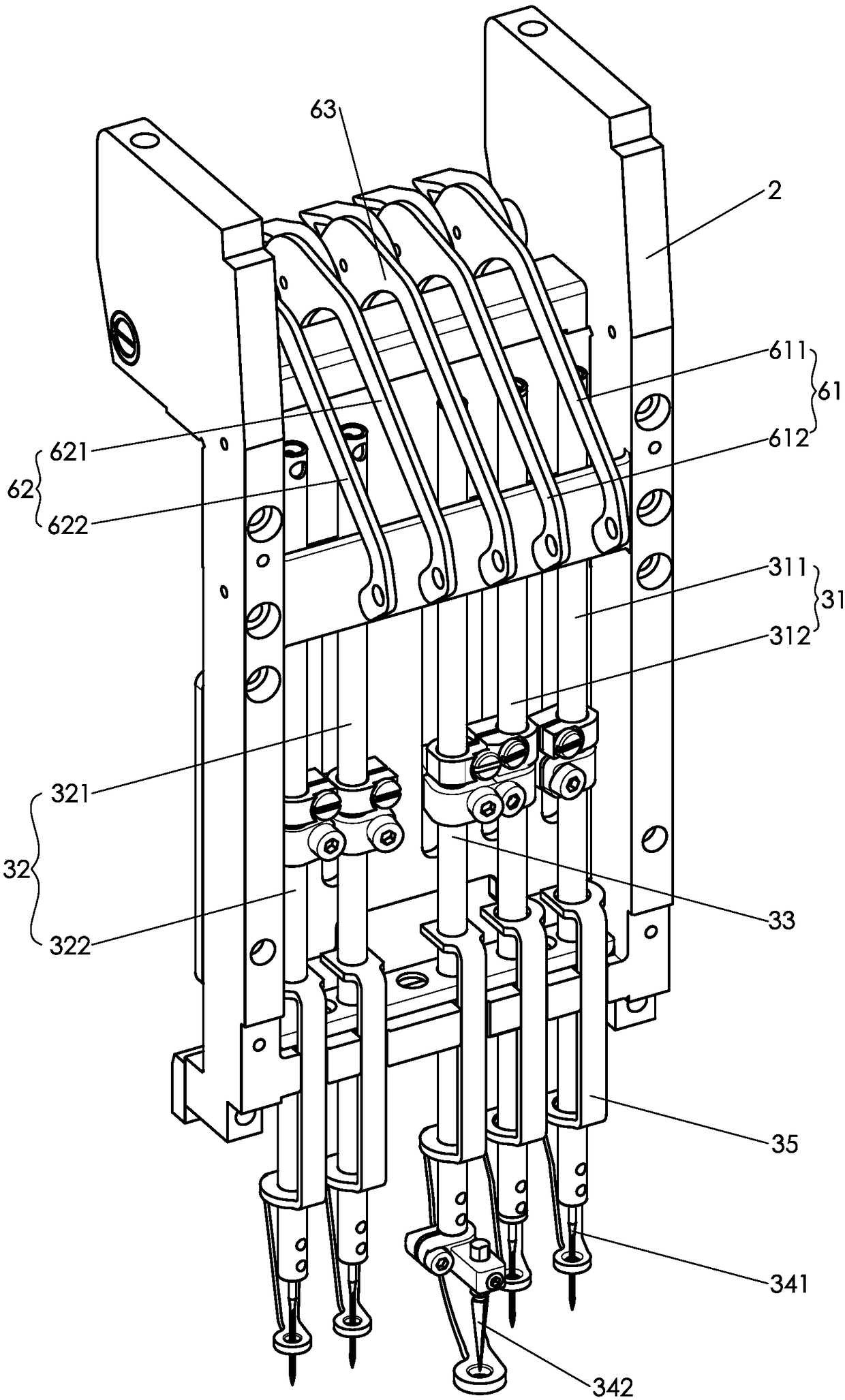
[0037] like figure 1 , figure 2 As shown, the embroidery machine head provided by Embodiment 1 of the present invention includes a casing 1 and a needle bar frame 2 arranged on the casing, and the needle bar frame can move back and forth laterally relative to the casing. The needle bar frame is provided with first needle bar 31, second needle bar 32 and carved hole needle bar 33, is provided with two needle bar drivers 4 on the casing, when one needle bar driver drives the carved hole needle bar, the other The needle bar driver is staggered with the first needle bar and the second needle bar in the moving direction of the needle bar frame and is in no-load.

[0038] The embroidery needle bar and the engraving needle bar are set on the machine head at the same time. When the fabric needs to be engraved at the head, the needle bar driver can drive the engraving needle bar to move back and forth. There is no need to shut down the machine head to replace the needles. On the pre...

Embodiment 2

[0067] The difference between Embodiment 2 of the present invention and Embodiment 1 above is that the machine needles at the bottom ends of needle bar I311 and needle bar III321 are replaced with engraved needles, and thread take-up lever I611 and thread take-up lever III621 are not threaded.

[0068] The machine head can realize the function of engraving holes on the flat head. At this time, the protrusions on the needle bar I and the needle bar III are respectively inserted into the grooves 41 on the two needle bar drivers 4, and the two thread take-up rollers 72 are respectively located on the pick-up In the open slot 25 of wire rod I and thread take-up rod III rear end. When the transmission shaft 15 rotates, the first cam and the transmission mechanism drive the needle bar I and the needle bar III to move up and down to realize the flat-headed double-needle carving hole. The thread roller drives the thread take-up lever Ⅰ and thread take-up lever Ⅲ to swing up and down f...

Embodiment 3

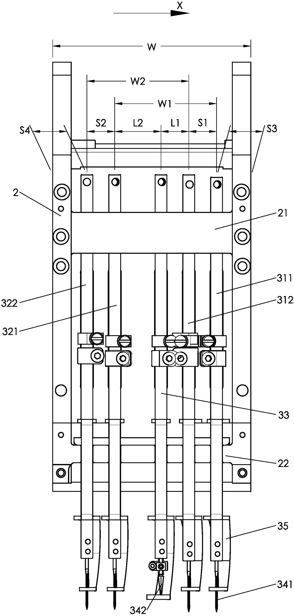
[0076] like Figure 11 As shown, the difference between the third embodiment of the present invention and the above-mentioned first embodiment is that the needle bar frame 2 moves left and right relative to the casing 1, and the direction shown by X' in the figure is the forward direction of the needle bar frame relative to the casing , the opposite direction of X' is the direction in which the needle bar frame moves back and resets relative to the casing.

[0077] At this time, needle bar I 311, needle bar II 312, carved hole needle bar 33, needle bar III 321 and needle bar IV 322 are arranged on the needle bar frame 2 from right to left along the needle bar frame 2, that is, needle bar I, needle bar II , carved hole needle bar, needle bar III and needle bar IV are sequentially arranged on the needle bar frame from back to front along the moving direction X' when the needle bar frame advances. The center distance between the needle bar III and the needle bar IV is S2, the ce...


PUM


Abstract

The invention discloses an embroidery machine head and an embroidery machine and belongs to the technical field of embroidery machines. The head comprises a casing and a needle bar frame arranged on the casing, wherein the needle bar frame can horizontally move back and forth relative to the casing, a first needle bar, a second needle bar and a boring needle bar are arranged on the needle bar frame, and two needle bar drivers are arranged on the casing; when one needle bar driver drives the boring needle bar, the other needle bar driver is staggered with the first needle bar and the second needle bar in the moving direction of the needle bar frame and is in a no-load state. Alternative head boring is realized through back and forth movement of the boring needle bar under the drive of the needle bar drivers, the head is not required to be shut down for replacement of needles, and the functions and applications of the head are enriched. Separation and reunion are realized by corresponding or staggering the needle bar drivers with the needle bars in the moving direction of the needle bar frame, electromagnets and drive parts driving the needle bar drivers to rotate under the drive ofthe electromagnets are not required to be added to the head, the structure of the head is advantageously simplified, time consumption for assembling of the head is reduced, and the production cost ofthe head is controlled.

Description

technical field [0001] The invention relates to the technical field of embroidery machines, in particular to an embroidery machine head, and in addition, the invention also relates to an embroidery machine using the head. Background technique [0002] With the advancement of science and technology, computerized embroidery machines have now become the main mechanical equipment in the embroidery industry, and the head of the embroidery machine is an important structure of the embroidery machine. When adopting the existing embroidery machine for engraved embroidery, it is necessary to shut down the machine first, replace the needles on some needle positions with engraved needles, and then restart to achieve the purpose of engraving the holes first and then wrapping the embroidery. The operation is complicated and unnecessary. It is beneficial to ensure the processing efficiency. When engraving holes on the partition, in order to avoid the effect of other needle bars used for e...

Claims


Application Information

Patent Timeline
Patent Type & Authority Applications(China)
IPC IPC(8): D05C7/04D05C11/00D05C11/06D05C13/00
CPCD05C7/04D05C11/00D05C11/06D05C13/00
Inventor 王海江
Owner ZHEJIANG XINSHENG SEWING EQUIP
Why Eureka
Try Eureka