
A cantilever beam structure

A cantilever beam and main beam technology, applied in the field of load-bearing structural parts, can solve problems such as large stress and deformation, structural damage and failure of cantilever beams, achieve uniform stress dispersion, improve structural stress, and relieve local stress concentration.

Inactive Publication Date: 2019-11-22
AEROSPACE HIWING HARBIN TITANIUM IND
View PDF5 Cites 0 Cited by
  • Summary
  • Abstract
  • Description
  • Claims
  • Application Information

AI Technical Summary

Problems solved by technology

[0003] In order to solve the problem that the cantilever beam structure in the prior art is in use, due to various concentrated loads, distributed loads, bending moments and torques, large stress and deformation may occur in any part of the beam, thus To solve the problem of damage or failure of the cantilever beam structure, the present invention provides a cantilever beam. The structure of the cantilever beam has a strong beam bearing capacity, and the force of the cantilever beam is reasonable during use by improving the structural force through reasonable design. It is not easy to be damaged and has a long service life. The specific scheme adopted is as follows:

Method used


Image

  • A cantilever beam structure
  • A cantilever beam structure
  • A cantilever beam structure

Examples


Embodiment approach 1

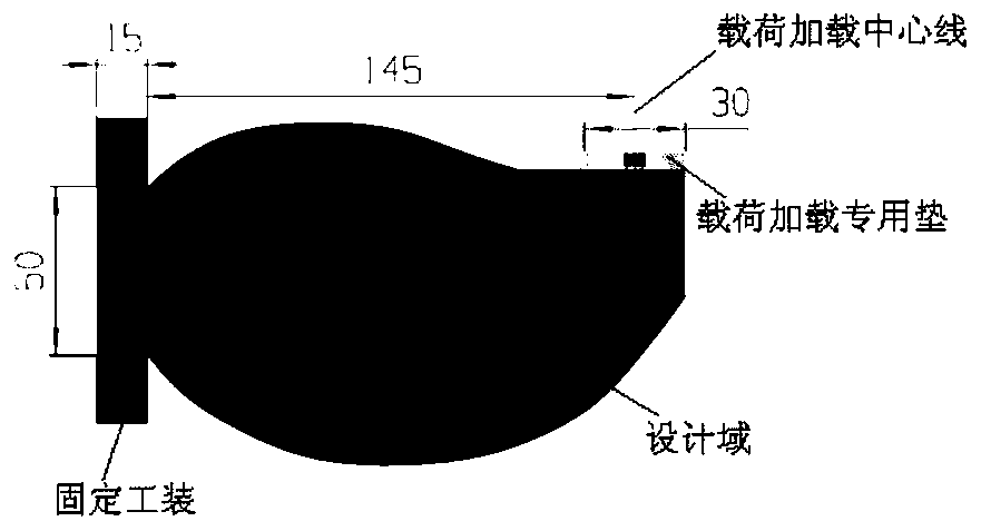
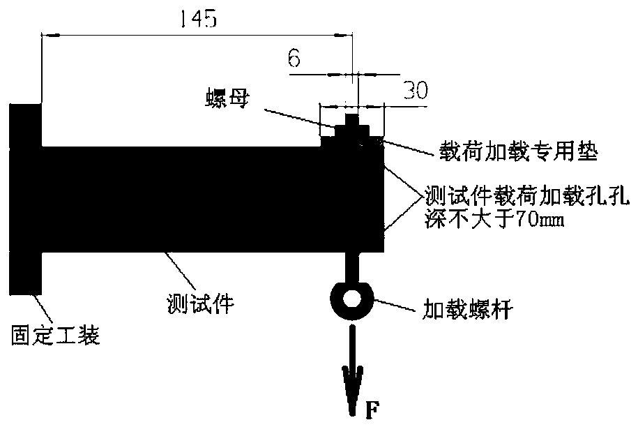
[0055] Such as Figure 10 , 11 As shown in and 15, the cantilever beam structure includes a fixed part 1, a main beam 2, a load-bearing tendon 3, two loading part load-input tendons 4 and a loading tunnel 5; wherein: the lower surface of one end of the main beam 2 is vertically fixedly connected There is a fixed part 1; the other end of the main beam 2 is provided with a load loading hole 7 penetrating through its upper surface and lower surface, and the lower surface of the main beam 2 is provided with two loading part force-inputting ribs 4 on both sides of the load loading hole 7 The two load-inputting ribs 4 intersect in the loading tunnel 5 and are fixedly connected to the outer wall of the loading tunnel 5; the tunnel position of the loading tunnel 5 is opposite to the tunnel position of the loading hole 7;

[0056] The load-bearing ribs 3 include the first load-bearing ribs 31, the second load-bearing ribs 32, the third load-bearing ribs 33, the fourth load-bearing rib...

Embodiment approach 2

[0059] In this embodiment, on the basis of Embodiment 1, the connection mode of the fixed part 1, the main girder 2, the load-bearing rib 3, the two loading part force-inputting ribs 4 and the loading tunnel 5 is further limited. In this embodiment, the fixed part 1 , the main girder 2, the load-bearing rib 3, the two loading portion load-input ribs 4 and the loading tunnel 5 are integrally processed and formed, and this processing method makes the structure stronger.

Embodiment approach 3

[0061] In this embodiment, a reinforcing rib 6 is added on the basis of the cantilever beam structure of Embodiment 1 or 2; and the midpoint of the third load-bearing rib 33, and one end is fixedly connected to the midpoint of the third load-bearing rib 33, and the other end is fixedly connected to the lower surface of the main beam 2.

[0062] In this embodiment, the purpose of improving the stress of the structure can be achieved by adding reinforcing ribs 6 locally on the load-bearing ribs, which can obviously improve the stress concentration phenomenon of the model structure and ensure the overall strength of the cantilever beam.


PUM


Abstract

The invention discloses a cantilever beam structure, belonging to the technical field of bearing structural members. The cantilever beam structure comprises a fixed part, a main beam, a bearing rib, two loading part force-conveying ribs and a loading channel, wherein the lower surface of one end of the main beam is vertically and fixedly connected with the fixed part; the other end of the main beam is provided with a loading hole penetrating the upper surface and the lower surface of the main beam; the lower surface of the main beam is provided with the two loading part force-conveying ribs atboth sides of the loading hole; the two loading part force-conveying ribs join each other in the loading channel and are fixedly connected with the outer wall of the loading channel; and the positionof the loading channel faces the channel position of the loading hole. The cantilever beam structure designed in the invention has better bearing capacity in limited bearing space and ensures high efficiency of a force conveying path; the designing of the bearing rib realizes uniform stress distribution, alleviates local stress concentration and avoids damage to a cantilever beam due to too greatlocal stress. The cantilever beam structure of the invention is applicable as a bearing structural member.

Description

technical field [0001] The invention relates to a cantilever beam structure, which belongs to the technical field of load-bearing structural parts. Background technique [0002] Cantilever beam structure is a relatively common structure in engineering, especially in mechanical design and architectural design. During the actual use of the cantilever beam structure, it is often subjected to various concentrated loads, distributed loads, bending moments and torques, and large stress and deformation may occur anywhere in the beam, so that the cantilever beam structure damage or failure. Therefore, how to maximize the bearing capacity of the beam is particularly important for the cantilever beam structure. Contents of the invention [0003] In order to solve the problem that the cantilever beam structure in the prior art is in use, due to various concentrated loads, distributed loads, bending moments and torques, large stress and deformation may occur in any part of the beam,...

Claims


Application Information

Patent Timeline
Patent Type & Authority Patents(China)
IPC IPC(8): E04C3/20G06F17/50
CPCE04C3/20G06F30/13G06F30/17G06F2119/06
Inventor 肖强卢新昌刘振军李新宇吴东辉费朝辉
Owner AEROSPACE HIWING HARBIN TITANIUM IND
Learn More