Magnetic field probe adopting isolation via-hole structure

A magnetic field probe and via technology, applied in the direction of the size/direction of the magnetic field, can solve the problems of weak signal current, errors, and inability to test and measure, and achieve the effect of improving the defects of measurement errors and ensuring accuracy.

Active Publication Date: 2018-06-22
BEIHANG UNIV
View PDF4 Cites 1 Cited by
  • Summary
  • Abstract
  • Description
  • Claims
  • Application Information

AI Technical Summary

Problems solved by technology

[0004] In order to overcome the deficiencies of the existing near-field magnetic field probes, the purpose of the present invention is to provide a magnetic field probe for near-field testing, which can solve the problem that the signal current cannot be tested due to the weak signal current during broadband testing and the introduction of The pitfalls of measurement error

Method used


Image

  • Magnetic field probe adopting isolation via-hole structure
  • Magnetic field probe adopting isolation via-hole structure
  • Magnetic field probe adopting isolation via-hole structure

Examples


Embodiment Construction

[0018] The practice of the present invention will be further described in detail below in conjunction with the accompanying drawings.

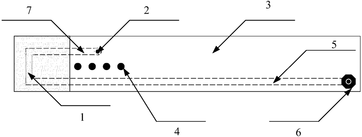
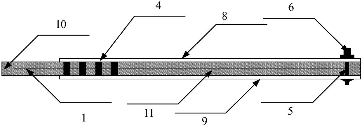
[0019] Such as figure 1 figure 2 As shown, this embodiment provides a magnetic field probe for near-field testing, including a symmetrical unshielded ring 1, a ground via 2, a strip line 3, an isolation via 4, a signal via 5, an adapter 6, Unshielded ring symmetrical arm extension line 7 , stripline shielding layer 8 , stripline lower shielding layer 9 , stripline medium 10 and stripline signal line 11 . The symmetrical unshielded ring 1 is located in the interlayer of the dielectric material 10 of the stripline 3 to ensure the strength of the symmetrical unshielded ring, one arm of the ring is directly connected to the signal line 11 of the stripline 3, and the other arm After the unshielded symmetrical ring extension line 7 is connected to the upper shielding layer 8 and the lower shielding layer 9 of the stripline 3 through the grounding...


PUM


Abstract

The invention adopts a magnetic field probe adopting an isolation via-hole structure. The magnetic field probe comprises a symmetric non-shielding ring, a grounding via hole, a strip line, isolation via holes, a signal via hole, an adapter, a non-shielding ring symmetric arm extension line, a strip line upper shielding layer, a strip line lower shielding layer, a strip line medium and a strip linesignal line. The symmetric non-shielding ring is arranged in the interlayer of the medium material of the strip line to ensure strength of the symmetric non-shielding ring; one arm of the symmetric non-shielding ring is directly connected with the strip line signal line, and the other arm is connected with the upper shielding layer and the lower shielding layer of the strip line through the non-shielding ring symmetric arm extension line and through the grounding via hole; the isolation via holes are arranged in the strip line, and are connected with the upper shielding layer and the lower shielding layer of the strip line, and meanwhile, are arranged between the grounding via hole and the strip line signal line; and the other end of the strip line signal line is connected with the adapter through the signal via hole.

Description

【Technical field】 [0001] The invention belongs to the field of electromagnetic field testing, and in particular relates to a magnetic field probe structure for testing a broadband high-sensitivity near-field magnetic field. Specifically, the near-field magnetic field distribution parameters of a tested object can be obtained through the near-field testing of the probe. 【Background technique】 [0002] With the rapid development of electrical engineering, electronic science and technology, computer technology, control theory and control engineering and other technologies, the application of electronic circuits in all walks of life occupies an indispensable position. The operating frequency band of electronic circuits is continuously expanding, and the integration and complexity are getting higher and higher. Any trace in the circuit may become a source of radiated magnetic field. Coupling between different trace radiations is one of the main causes of system-level EMC problems...

Claims


Application Information

Patent Timeline
Patent Type & Authority Applications(China)
IPC IPC(8): G01R33/02
CPCG01R33/02
Inventor 阎照文刘伟
Owner BEIHANG UNIV
Why Eureka
Try Eureka