A modular motor stator structure

A motor stator, modular technology, applied in the direction of magnetic circuit shape/style/structure, winding conductor shape/style/structure, electromechanical devices, etc., can solve the problem of inability to greatly reduce end loss and temperature, inconvenient motor maintenance, Transformation, time-consuming and other issues to achieve the effect of ensuring control flexibility and controllability, improving fault tolerance and reliability, and reducing production process

Inactive Publication Date: 2019-06-25
ZHENGZHOU UNIVERSITY OF LIGHT INDUSTRY
View PDF6 Cites 0 Cited by
  • Summary
  • Abstract
  • Description
  • Claims
  • Application Information

AI Technical Summary

Problems solved by technology

However, these methods can only reduce the heat dissipation problem at the end to a certain extent, and cannot greatly reduce the loss and temperature at the end.
At the same time, it is impossible to shorten the length of the motor and reduce the volume of the motor
[0004] In the normal working process of traditional motors, it is difficult to control the internal magnetic field of the motor, and it is difficult to achieve real-time control of the internal magnetic field of the motor, resulting in large harmonic losses of the motor; at the same time, it is difficult to change the number of motor poles, and it is impossible to adjust the motor poles according to actual requirements. make timely adjustments accordingly
The traditional method is to use transfer switches or contactors to change the stator winding connection to realize the pole-changing speed regulation of the motor under the condition that the power frequency remains unchanged. This method has a small range of pole adjustment and low reliability.
[0005] According to the traditional motor manufacturing process, the process of assembling the motor stator is cumbersome and time-consuming, and it is not suitable to disassemble after the assembly is completed, which is not convenient for maintenance and modification of the motor

Method used


Image

  • A modular motor stator structure
  • A modular motor stator structure
  • A modular motor stator structure

Examples


Embodiment Construction

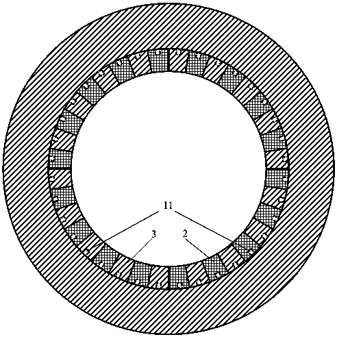
[0032] The following is attached Figure 1 to Figure 7 The specific implementation manner of this embodiment will be described in detail.

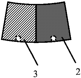
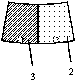
[0033] A modularized motor stator structure of the present invention includes a stator, the inner ring of the stator yoke 1 is evenly arranged with a plurality of protrusion groups along the circumferential direction, and each protrusion group includes a plurality of radially inward protrusions protruding from the stator The inner ring of the yoke 1 is provided with a protrusion 11 arranged in the axial direction; the inner ring of the stator yoke 1 is also provided with a magnetic strip 2 and a stator tooth 3 alternately along the circumferential direction, and the magnetic strip 2 and the stator tooth 3 are connected with the The protruding groups are arranged correspondingly, and the magnetic strip 2 and the stator tooth part 3 are provided with a groove matching the corresponding convex part 11, and the magnetic conductive strip 2 and ...


PUM


Abstract

The invention discloses a modular motor stator structure. The modular motor stator structure comprises a stator; the inner ring of a stator yoke is provided with multiple raised groups which are arranged uniformly along a circumferential direction; each raised group comprises at least one raised part which is raised inwardly along a radial direction out of the inner ring of the stator yoke and isarranged along an axial direction; magnetic strips and stator tooth parts are alternatively arranged at the inner side of the inner ring of the stator yoke along the circumferential direction; the magnetic strips and the stator tooth parts are arranged correspondingly to the raised groups; the magnetic strips and the stator tooth parts are provided with grooves matched with the corresponding raised parts; and the magnetic strips and the stator tooth parts are clamped with the corresponding raised parts at the grooves to form a concealed buckling-type structure. modular splitting on the motor can be realized, the motor production process is reduced, and the making period is shortened.

Description

technical field [0001] The invention relates to the technical field of motors, in particular to a modularized motor stator structure. Background technique [0002] Motor is the power source of social production and life. With the continuous improvement of society's requirements for production and life, higher requirements are put forward for the operation reliability, flexibility and controllability of the motor. [0003] When the motor is working normally, due to the traditional end winding structure of the motor, a large amount of loss will also be generated due to the existence of end winding resistance, which will cause the end of the motor to overheat. In severe cases, the insulation of the end winding will be damaged and the motor will fail. At present, the traditional method is to pour glue at the end of the motor to replace the air, to ensure that it is reliably insulated, and to increase the thermal conductivity between the end of the casing and the winding, so that...

Claims


Application Information

Patent Timeline
Patent Type & Authority Patents(China)
IPC IPC(8): H02K1/14H02K1/16H02K1/20H02K3/18
CPCH02K1/146H02K1/165H02K1/20H02K3/18
Inventor 邱洪波魏彦企杨存祥伊然李伟力时长敏
Owner ZHENGZHOU UNIVERSITY OF LIGHT INDUSTRY
Why Eureka
Try Eureka