

Dust-removal sweeping device
A technology of sweeping rollers and trolleys, which is applied in the direction of cleaning carpets, cleaning floors, and manual sweeping machines. It can solve the problems of high cost of sweeping vehicles, large volume of sweeping vehicles, and complex structure, so as to reduce labor intensity and reduce the operation of compressing garbage. , Improve the effect of processing efficiency
Active Publication Date: 2018-06-26
宁波梦居智能科技有限公司
View PDF4 Cites 8 Cited by
- Summary
- Abstract
- Description
- Claims
- Application Information
AI Technical Summary
Problems solved by technology
Modern sweepers are expensive, and units without financial strength want to buy them but can't afford them
Moreover, the existing sweeping vehicles are bulky, complex in structure and difficult to maintain.
Method used
View moreImage
Smart ImageViewing Examples

Examples
Embodiment Construction
[0013] The present invention is described in further detail below by specific embodiments:
Login to View More PUM
 Abstract
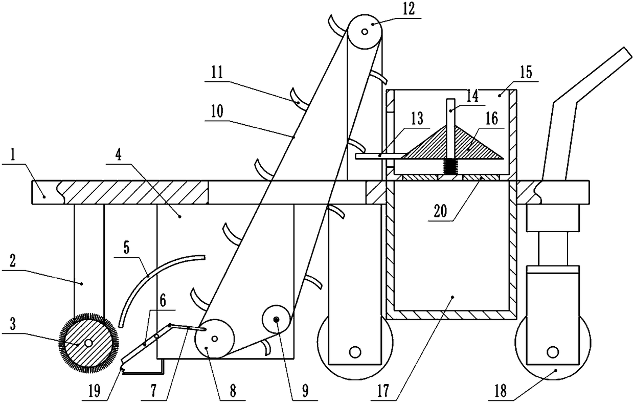
The invention belongs to the technical field of environmental protection equipment, and specifically discloses a dust-removal sweeping device. The device comprises a trolley, and the front end of thetrolley is provided with a sweeping roller. The upper end of the middle of the trolley is provided with a driving wheel, and the lower end of the middle of the trolley is rotatably connected with a first driven wheel and a second driven wheel. A conveying belt is connected among the driving wheel, the first driven wheel and the second driven wheel. A plurality of clapboards are connected to the conveying belt. A material throwing plate is hinged to a lower bracket, a connecting rod is hinged to the material throwing plate, and the other end of the connecting rod is hinged to the eccentric portion of the end face of the first driven wheel. The upper portion of the trolley is provided with a compression box, the compression box is internally and fixedly connected with a central shaft, the central shaft is slidingly connected with a conical material pressing plate, and a spring is connected between the material pressing plate and the bottom wall of the compression box. A pressing rod is fixedly connected to the lower portion of the material pressing plate, and the end portion of the pressing rod is located below the driving wheel. A garbage box is arranged below the compression box, and a pressure door is connected between the compression box and the garbage box. The dust-removal sweeping device cleans away garbage and compresses the garbage at the same time.
Description
technical field [0001] The invention belongs to the technical field of environmental protection equipment, and in particular relates to a dust removal and floor sweeping device. Background technique [0002] Sweeping the floor in public places is a hard job, not only the dust affects the health of workers, but also the labor intensity is high and the working hours are long. For example, for the cleaning of squares, streets and expressways, laborers use brooms to clean them. Due to the large area, they hope to finish the work in the early morning. Otherwise, it will affect road traffic and affect the public's exercise activities in the square. So they got up in the middle of the night and rushed to work. Their daily life was not normal, and the temperature at night was low, which made their work harder. Low work efficiency is the main problem when sweeping large areas of roads and squares, and it is also the reason why sweepers need to get up in the middle of the night to wo...
Claims
Login to View More Application Information
Patent Timeline
 Patent Type & AuthorityApplications(China)
IPC IPC(8): A47L11/24A47L11/40
CPCA47L11/24A47L11/40A47L11/4013
Inventor陈灿刚周宇震朱军
Owner宁波梦居智能科技有限公司