
Intelligent infusion rack

An infusion stand and intelligent technology, applied in the field of intelligent infusion stand, can solve the problems of wasting human resources, inconvenient to use, troublesome, etc., and achieve the effect of compact structure, easy portability and smooth movement

Pending Publication Date: 2018-06-26
SICHUAN CANCER HOSPITAL
View PDF3 Cites 19 Cited by
  • Summary
  • Abstract
  • Description
  • Claims
  • Application Information

AI Technical Summary

Problems solved by technology

[0004] However, the existing mobile infusion stands need to be pushed by people or medical staff to move, which is very inconvenient to use, especially in the process of transferring emergency patients to emergency rooms or operating rooms, special people are required to push the mobile The infusion stand follows the patient, which is both troublesome and a waste of human resources

Method used


Image

  • Intelligent infusion rack
  • Intelligent infusion rack
  • Intelligent infusion rack

Examples


Embodiment 1

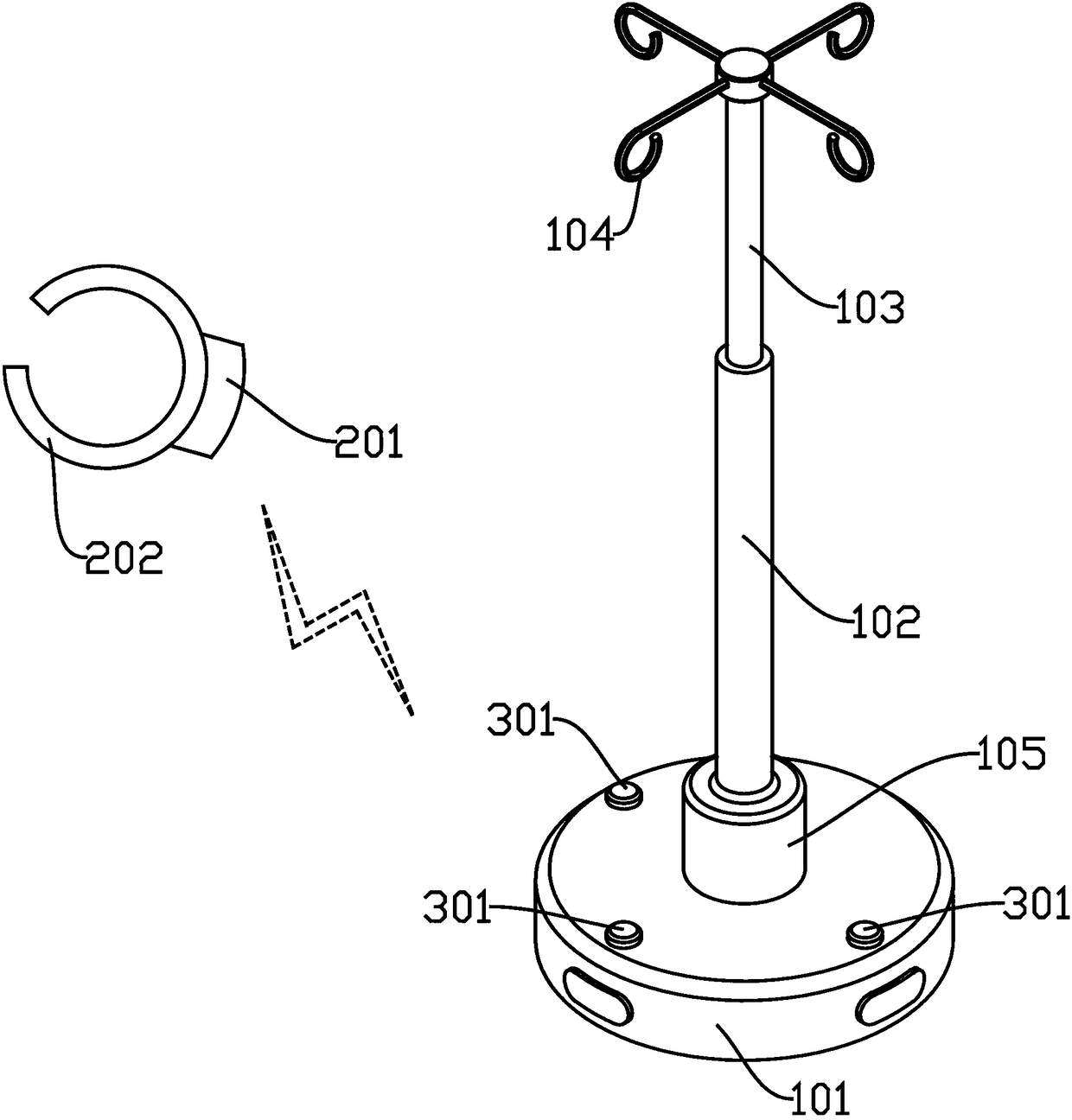
[0044] Such as figure 1 As shown, an intelligent infusion stand is provided in this embodiment, including an infusion stand body, a controller, and an ultrasonic transmitter 201. The infusion stand body includes a base 101 and a bracket, and the bracket is vertically arranged on the base 101. There are several hooks 104, and the hooks 104 are mainly used for hanging infusion bags or infusion bottles;

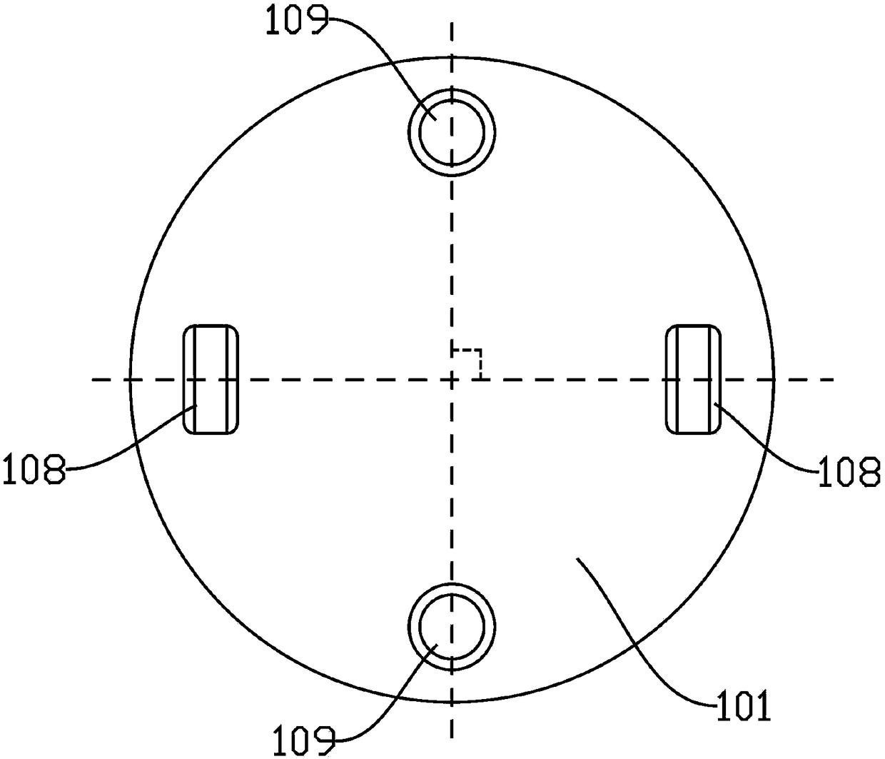
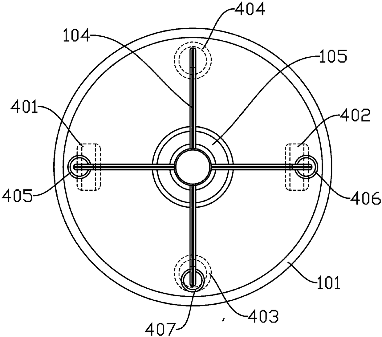
[0045] Several wheels are arranged on the bottom surface of the base 101, and the controller can control the forward / reverse installation and acceleration / deceleration of the wheels. Several ultrasonic receivers 301 are arranged on the base 101, and the ultrasonic transmitter 201 is used to be detachably arranged on the body of the infusion patient. And transmit ultrasonic signal under the control of controller, ultrasonic receiver 301 is used for receiving ultrasonic signal and transmits to controller, and controller is used for calculating the time difference that each ultraso...

Embodiment 2

[0058] The main difference between this embodiment 2 and the above-mentioned embodiment 1 is that, as Image 6 As shown, in this embodiment, the base 101 of the intelligent infusion stand also includes several anti-collision sensors 302, and several anti-collision sensors 302 are evenly arranged on the side wall of the base 101, and the anti-collision sensors 302 are used to detect the base 101 and the surrounding area. The distance between obstacles to avoid collisions; as shown in the figure, the size of the base 101 is the largest size of the intelligent infusion stand along the direction perpendicular to the axis, as long as the base 101 does not collide, the rest will not collide; use The data detected by the anti-collision sensor 302, while realizing the anti-collision function, the controller can also perform path planning, so as to detour or stop when an obstacle is detected.

[0059] In this embodiment, the anti-collision sensor 302 can adopt a laser ranging sensor or...


PUM


Abstract

The invention relates to an intelligent infusion rack which comprises an infusion rack body, a controller and an ultrasonic transmitter. The infusion rack body comprises a base and a support. The support is arranged on the base and provided with a plurality of hooks. The hooks are used for hanging infusion bags or infusion bottles. The base is provided with a plurality of wheels and a plurality ofultrasonic receivers. The ultrasonic transmitter is used for being detachably arranged on a body of an infusion patient and transmitting ultrasonic signals under the control of the controller. The ultrasonic receivers are used for receiving the ultrasonic signals and transmitting the ultrasonic signals to the controller. The controller is used for calculating the difference of time when the ultrasonic receivers receive the ultrasonic signals and calculating the direction and distance of the ultrasonic transmitter according to the difference of time, thereby controlling the movement of the wheels towards the ultrasonic transmitter. The intelligent infusion rack is compact in structure and convenient to move, and the automatic lifting function and the automatic following function can be realized.

Description

technical field [0001] The invention relates to the technical field of medical equipment, in particular to an intelligent infusion stand. Background technique [0002] At present, infusion is a relatively routine treatment method in hospitals. The time for ordinary infusion basically takes 2 or 3 hours, and it takes even longer for severe cases. Since infusion is usually performed in wards, operating rooms, emergency rooms, etc., the location of infusion They are all relatively fixed, so that the movement of the infusion patient is greatly restricted during the infusion. [0003] The appearance of the mobile infusion stand has brought convenience to the infusion patients. With the use of the mobile infusion stand, the infusion patients can perform appropriate activities in the hospital, such as walking in the corridor, going to the toilet and doing examinations. [0004] However, the existing mobile infusion stands need to be pushed by people or medical staff to move, which...

Claims


Application Information

Patent Timeline
IPC IPC(8): A61M5/14G05D1/02
CPCA61M5/1417G05D1/0214G05D1/0255A61M2205/18A61M2205/3576
Inventor 李柏森文敏
Owner SICHUAN CANCER HOSPITAL
Learn More