Liquid squeezing device for fibers or fiber webs
A fiber web and fiber technology, applied in the field of liquid removal of textile materials, can solve the problems of low dehydration rate, affecting the dehydration effect of fibers, fiber layers and similar objects
- Summary
- Abstract
- Description
- Claims
- Application Information
AI Technical Summary
Problems solved by technology
Method used
Image
Examples
Embodiment 1
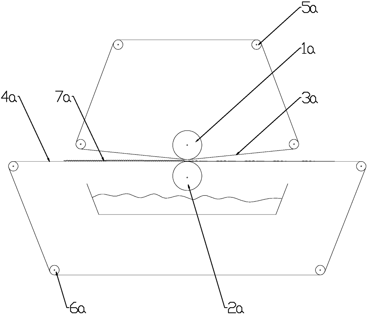
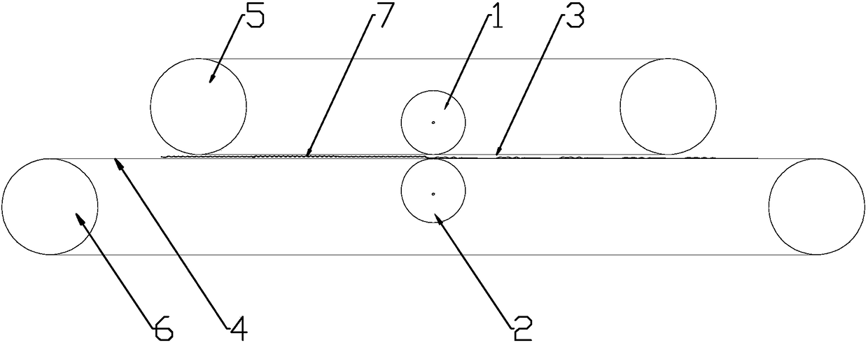
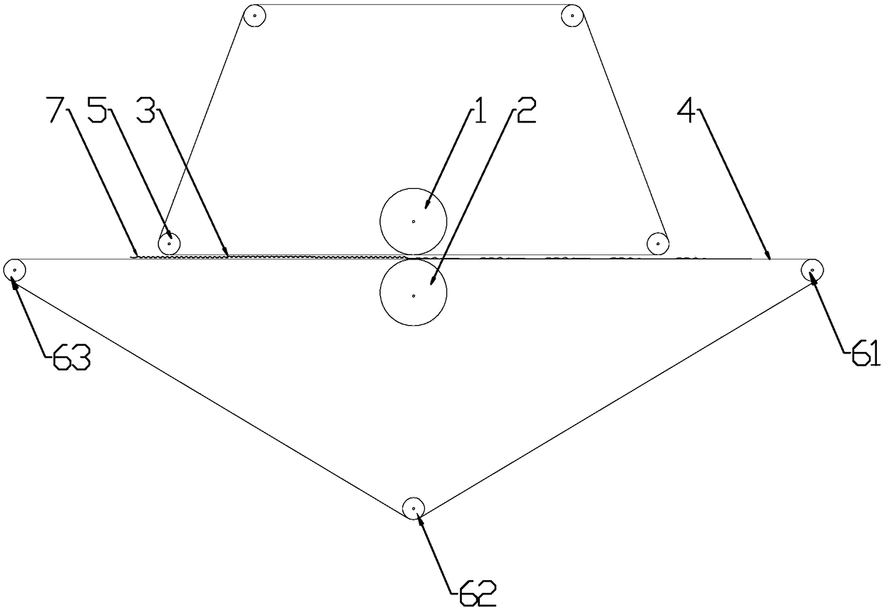
[0034]In this embodiment, a device for squeezing liquid for fibers or fiber webs includes two rollers and two conveying mechanisms, at least one of which is a driving roller in the two rollers; And the guide belt tensioned on the driving roller and the idler roller; there is a space between the two guide belts to accommodate the passage of fibers, fiber webs or the like, and the two passages that constitute the passage space of the fibers, fiber webs or the like The parts of the two guide belts are parallel to each other, and the two rolls are respectively installed at the positions corresponding to the passage spaces of the two guide belts.
[0035] Specifically in this case, taking liquid rolling as an example, combined with figure 2 , the driving rollers in the two conveying mechanisms are respectively called the first driving roller 5 and the second driving roller 6, and the rollers are respectively called the first roller 1 and the second roller 2. Then, guide belt one 3...
Embodiment 2
[0037] The setting and working principle of this embodiment are the same as that of Embodiment 1, the difference lies in: combining figure 2 , the first driving roller 5 is provided with a pair, and the outer diameter of the first driving roller 5 is larger than the first roller 1, and the guide belt 3 is set on the pair of first driving rollers 5, and the first roller 1 is located near the guide belt 3. The loop on one side of the conduction band 24.
[0038] In order to achieve further usage requirements, the above scheme can be further set as follows:
[0039] The first roller 1 is provided with at least one, such as figure 2 , image 3 , Figure 4 , set only one, such as Figure 5 Set two (i.e. Figure 5 In the first roll one 11, the first roll two 12), as Figure 6 Three settings are shown (i.e. Figure 6 In the first roll one 11, the first roll two 12, the first roll three 13), as Figure 7 The five settings shown (ie Figure 7 In the first roll one 11, the fi...
Embodiment 3
[0042] The setting and working principle of this embodiment are the same as that of Embodiment 1, the difference lies in: combining figure 2 , the second driving roller 6 is provided with a pair, the outer diameter of the second driving roller 6 is larger than the second roller 2, the guide belt 2 and the guide belt 2 4 are set on the pair of second driving rollers 6, and the second roller 2 is located at the guide belt The second conduction band 2 4 is close to the loop on the side of the conduction band 1 3 .
[0043] In order to achieve further usage requirements, the above scheme can be further set as follows:
[0044] The second roller 2 is provided with at least one, such as figure 2 , image 3 , Figure 4 , set only one, such as Figure 5 Set two (i.e. Figure 5 In the second roller one 21, the second roller two 22), as Figure 6 Three settings are shown (i.e. Figure 6 In the second roll one 21, the second roll two 22, the second roll three 23), as Figure 7 ...
PUM
 Abstract
Description
Claims
Application Information
 - R&D
- Intellectual Property
- Life Sciences
- Materials
- Tech Scout
- Unparalleled Data Quality
- Higher Quality Content
- 60% Fewer Hallucinations
Browse by: Latest US Patents, China's latest patents, Technical Efficacy Thesaurus, Application Domain, Technology Topic, Popular Technical Reports.
© 2025 PatSnap. All rights reserved.Legal|Privacy policy|Modern Slavery Act Transparency Statement|Sitemap|About US| Contact US: help@patsnap.com


