Device and method for testing MIMO scheme system

A test device and test object technology, applied in the transmission system, radio transmission system, diversity/multi-antenna system, etc., can solve the problems of large-scale equipment, large circuit scale, manufacturing cost and power consumption, etc., and reach the circuit scale zoom out effect

Active Publication Date: 2018-06-26
ANRITSU CORP
View PDF7 Cites 0 Cited by
  • Summary
  • Abstract
  • Description
  • Claims
  • Application Information

AI Technical Summary

Problems solved by technology

[0027] In the test device with the above-mentioned structure, in a system that performs beamforming processing, the number N of arrayed transmitting antennas becomes very large, for example, 128, and the time required to perform parallel Fourier transform processing with N sequences 128 groups are required for the area signal generating unit 13, and the circuit scale becomes very large
[

Method used


Image

  • Device and method for testing MIMO scheme system
  • Device and method for testing MIMO scheme system
  • Device and method for testing MIMO scheme system

Examples


Embodiment Construction

[0077] Hereinafter, the embodiments of the present invention will be described based on the drawings. Before describing the specific structure, the principle of the test device of the present invention will be described first.

[0078] The present invention can be used as a propagation path simulator when N×M MIMO (N>M) is implemented in the multi-carrier modulation methods such as OFDM, UFMC, GFDM, FBMC, etc., such as 3D-MIMO / Massive-MIMO That is especially effective when the number of transmitting antennas is very large compared to the number of receiving antennas. Hereinafter, as a modulation method, the description will be mainly focused on OFDM.

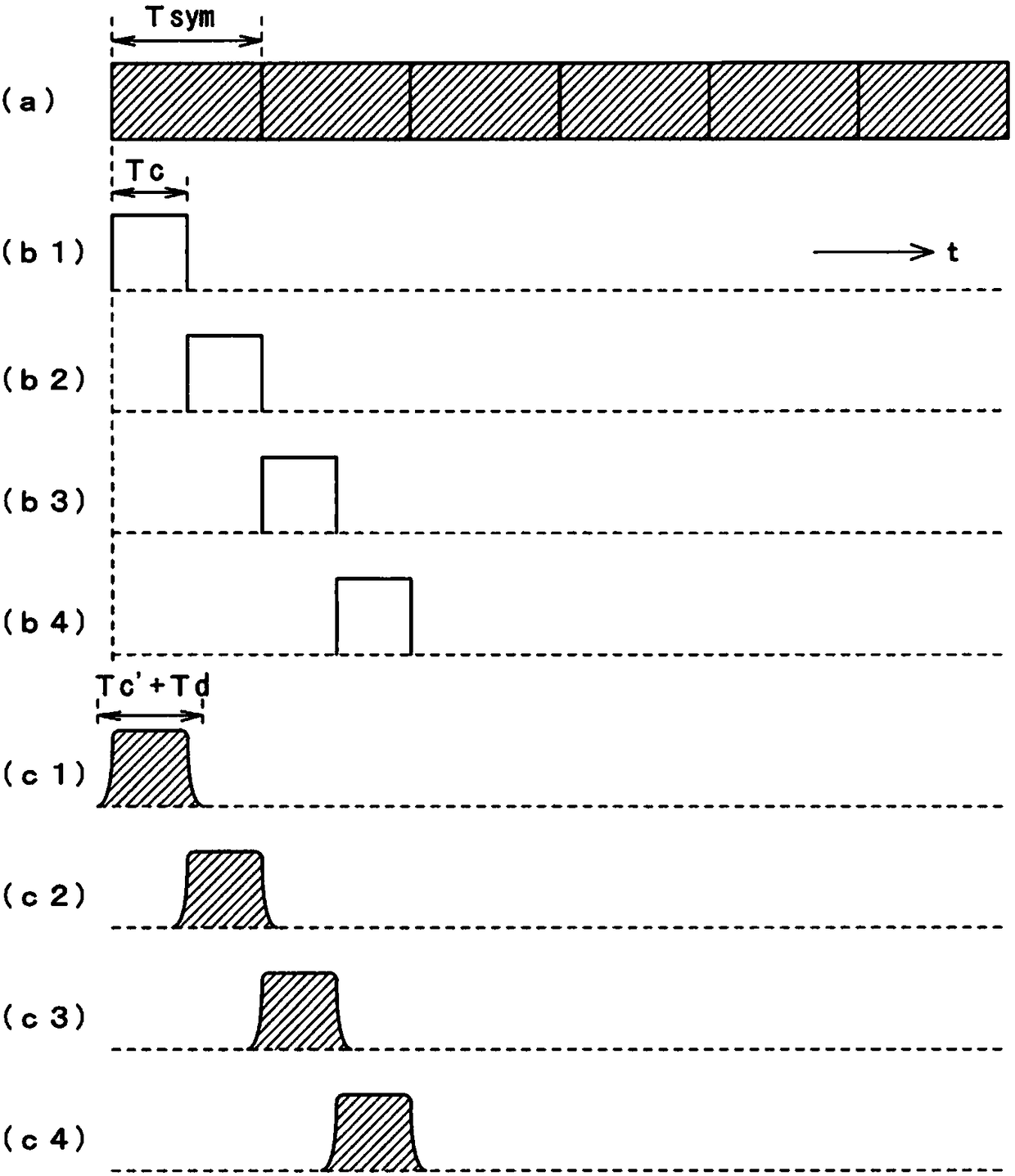
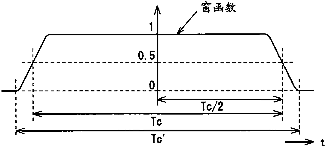
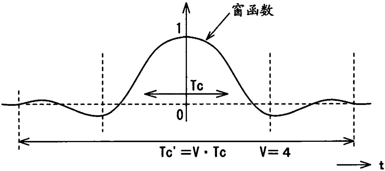
[0079] In the present invention, the following formula (1), for each time span (every Tc) to the extent that the time change of the characteristics of the MIMO propagation path can be ignored, the characteristics of the MIMO propagation path are set to be constant within the time span, and MIMO propagation path processing is perform...


PUM


Abstract

The invention provides a testing device for a system, and the device is small in circuit scale and uses little electricity. The system combines multi-carrier, a MIMO scheme, and beam forming processing. For modulation signals of each carrier of an R layer quantity output by a layer frequency domain signal generation unit (31), a window function arithmetic operation unit (32) performs convolution arithmetic operation of frequency characteristics of a window function. On another aspect, for a beam forming equivalence arithmetic operation unit (52) performs an arithmetic operation process equivalent to the beam forming process with the input of propagation channel characteristics of each path which are output by a fading setting unit (51), and a Fourier transform unit (53) performs Fourier transform with the input of the arithmetic operation results. An arithmetic operation unit (54) performs multiplication on two operation results Ht and Fsym, obtains spectrum information of signals to be received in receiving antennas, and converts the obtained spectrum information into signals in the time domain through inverse Fourier transform processes performed by a time domain signal generation unit. A shift addition unit (34) shifts and adds the converted signals, to generate received signals of the receiving antennas.

Description

Technical field [0001] The present invention relates to a technique for reducing the circuit scale of a test device that has a terminal corresponding to the MIMO (Multi Input Multi Output) method or a circuit substrate and integrated circuit built in the terminal as a test object, and The function of performing fading processing on the propagation path of N×M channels assumed between the transmitting antenna and the receiving antenna. In the MIMO method, the number of antennas on the base station side is N and the number of antennas on the terminal side is M. Downlink signal. Background technique [0002] MIMO methods such as Picture 9 As shown, the downlink signals Stx1 to StxN toward the terminal side are transmitted from N (N=4 in this example) base station side antennas (hereinafter referred to as transmitting antennas) Atx1 to AtxN, and M (the In the example, M=2) Terminal side antennas (hereinafter referred to as receiving antennas) Arx1 to ArxM perform reception. [0003] ...

Claims


Application Information

Patent Timeline
IPC IPC(8): H04B17/391H04B7/0413H04B7/06
CPCH04B7/0413H04B7/0617H04B17/391H04B17/3911H04B17/102
Inventor 小林武史
Owner ANRITSU CORP
Why Eureka
Try Eureka