Conical extraction element with double flow channels and flow-through extraction method
A double-channel, conical technology, applied in chemical instruments and methods, solvent extraction, separation methods, etc., can solve problems such as low operating flexibility, unstable coacervate, and strict design requirements for sieve tray towers, so as to increase extraction The effect of increasing the speed and improving the effective utilization rate
- Summary
- Abstract
- Description
- Claims
- Application Information
AI Technical Summary
Problems solved by technology
Method used
Image
Examples
Embodiment 1
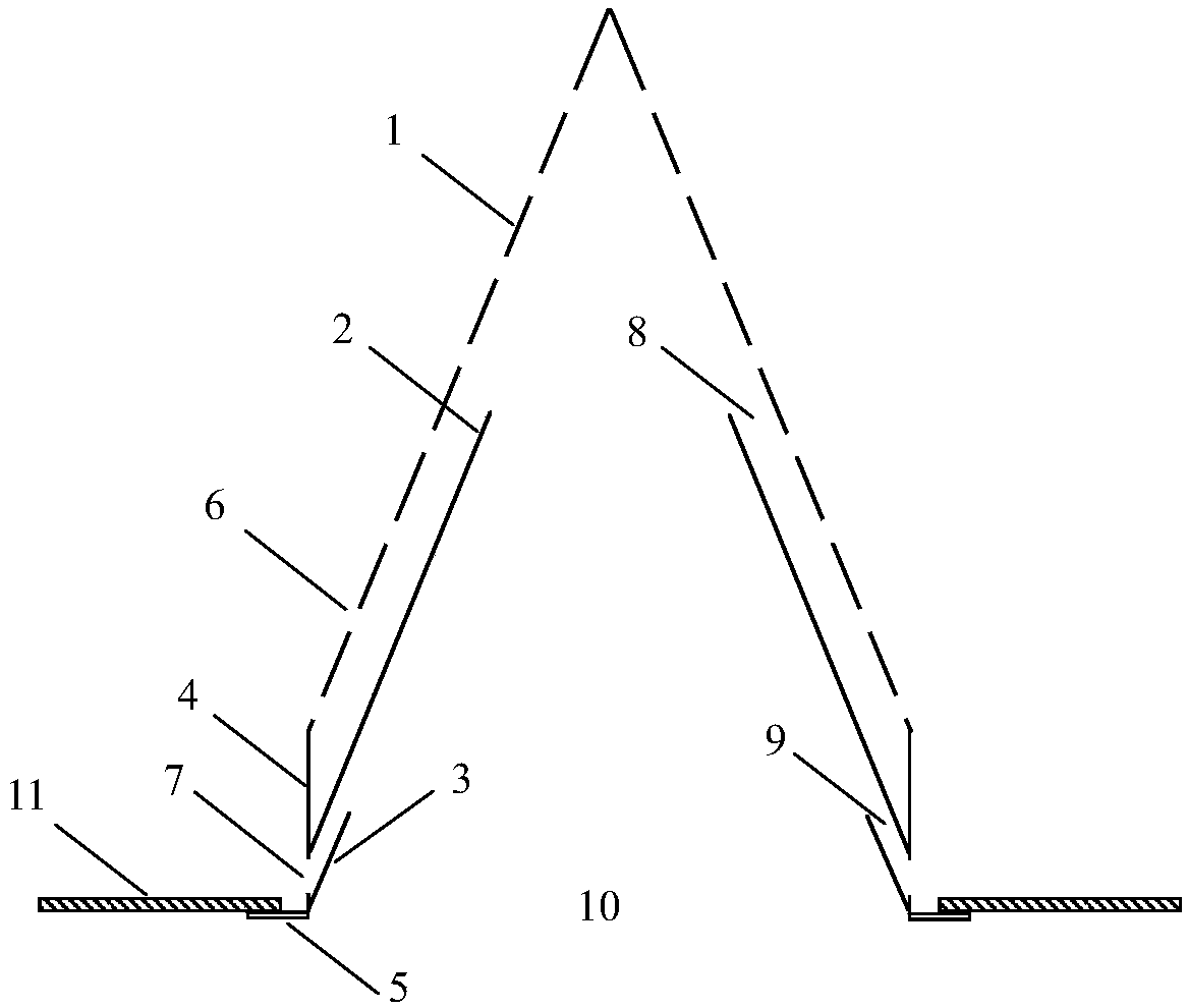
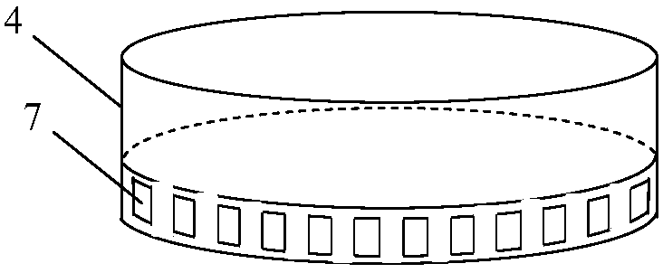
[0042] Figure 1-2 Represents a structural diagram of a dual-channel conical extraction element. Among them, the outer diameter of the bottom end of the upper conical cover plate 1 is 100 mm, the height of the conical cover plate 1 is 120 mm (the ratio of height to diameter is 1.2:1); the height of the conical baffle plate 2 is 78 mm (ratio to the height of the cover plate 1). 0.65:1); the height of the circular connecting pipe 4 is 40mm, and the height of the conical deflector 3 is 16mm (the height ratio of the connecting pipe 4 is 0.4:1); the lower side wall of the circular connecting pipe 4 is uniformly opened There are 24 rectangular flow-limiting holes 7 in a circle, the height of the rectangular holes is 10mm, and the width is 6mm.
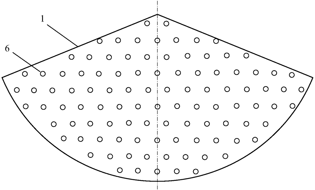
[0043] image 3 It is the expansion diagram of the conical cover plate 1, which is a fan-shaped sieve plate, and the distribution holes 6 on it are circular sieve holes, the specification is φ4~5mm, the hole spacing is 15mm, arranged in an...
Embodiment 2
[0047] Figure 1-2 Represents a structural diagram of a dual-channel conical extraction element. Among them, the outer diameter of the bottom end of the upper conical cover plate 1 is 80 mm, the height of the conical cover plate 1 is 84 mm (the ratio of height to diameter is 1.05:1); the height of the conical baffle plate 2 is 50 mm (ratio to the height of the cover plate 1 0.6:1); the height of the circular connecting pipe 4 is 36mm, and the height of the conical deflector 3 is 18mm (the height ratio of the connecting pipe 4 is 0.5:1); the lower side wall of the circular connecting pipe 4 is evenly opened There are 24 rectangular flow-limiting holes 7 in a circle, the height of the rectangular holes is 9mm, and the width is 5mm.
[0048] image 3 It is the expansion diagram of the conical cover plate 1, which is a fan-shaped sieve plate, and the distribution holes 6 on it are circular convex holes, the specification is φ3~4mm, the hole spacing is 12mm, arranged in an equila...
Embodiment 3
[0052] Figure 1-2 Represents a structural diagram of a dual-channel conical extraction element. Among them, the outer diameter of the bottom end of the upper conical cover plate 1 is 60 mm, the height of the conical cover plate 1 is 75 mm (the ratio of height to diameter is 1.25:1); the height of the conical baffle plate 2 is 40 mm (ratio to the height of the cover plate 1 0.53:1); the height of the circular connecting pipe 4 is 30mm, and the height of the conical deflector 3 is 18mm (the vertical height ratio of the connecting pipe 4 is 0.6:1); the lower side wall of the circular connecting pipe 4 A circle of rectangular flow-limiting holes 7 is evenly opened, and the total number is 24. The height of the rectangular holes is 8 mm, and the width is 4 mm.
[0053] Figure 4 It is the expansion diagram of the conical cover plate 1, which is a fan-shaped sieve plate, and the distribution holes 6 on it are circular sieve holes, the specification is φ2~3mm, the hole spacing is ...
PUM
| Property | Measurement | Unit |
|---|---|---|
| Outer diameter | aaaaa | aaaaa |
| Vertical height | aaaaa | aaaaa |
| Ring width | aaaaa | aaaaa |
Abstract
Description
Claims
Application Information
 - R&D
- Intellectual Property
- Life Sciences
- Materials
- Tech Scout
- Unparalleled Data Quality
- Higher Quality Content
- 60% Fewer Hallucinations
Browse by: Latest US Patents, China's latest patents, Technical Efficacy Thesaurus, Application Domain, Technology Topic, Popular Technical Reports.
© 2025 PatSnap. All rights reserved.Legal|Privacy policy|Modern Slavery Act Transparency Statement|Sitemap|About US| Contact US: help@patsnap.com


