
Double-station die cutting equipment for machining printed label roll

A double-station, label roll technology, applied in metal processing and other directions, can solve the problems of poor uniformity of peripheral cutting, affect product quality and aesthetics, and decline in cutting quality, so as to avoid inconsistent die-cutting quality and improve die-cutting processing Quality, improvement of production efficiency and the effect of production and processing quality

Pending Publication Date: 2018-06-29
QIANDA NEW MATERIAL CO LTD
View PDF0 Cites 4 Cited by
  • Summary
  • Abstract
  • Description
  • Claims
  • Application Information

AI Technical Summary

Problems solved by technology

[0003] In order to improve the uniformity of the die-cutting peripheral frame, a cutter is generally used to cut off the printed part during die-cutting, that is, the part on one side of the release paper is cut off more than the printed part. In the process of cutting, the existing cutting tool It is easy to process and cut off the release paper at the same time, which can not meet the production requirements. At the same time, the printed label roll is prone to fluctuate up and down during the conveying process, resulting in a sharp drop in the quality of cutting. In addition, before and after cutting, the existing The equipment cannot monitor whether the adjacent printed pattern is in a set position, resulting in poor uniformity when cutting the periphery, which affects the quality and aesthetics of the product

Method used


Image

  • Double-station die cutting equipment for machining printed label roll
  • Double-station die cutting equipment for machining printed label roll
  • Double-station die cutting equipment for machining printed label roll

Examples


Embodiment Construction

[0070] The following are specific embodiments of the invention and in conjunction with the accompanying drawings, the technical solutions of the present invention are further described, but the present invention is not limited to these embodiments.

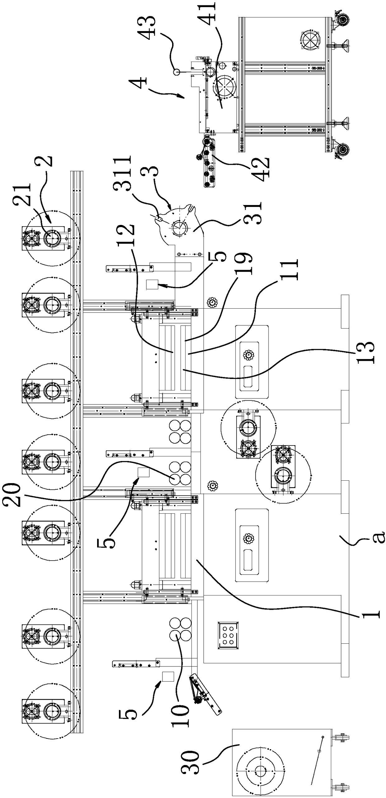
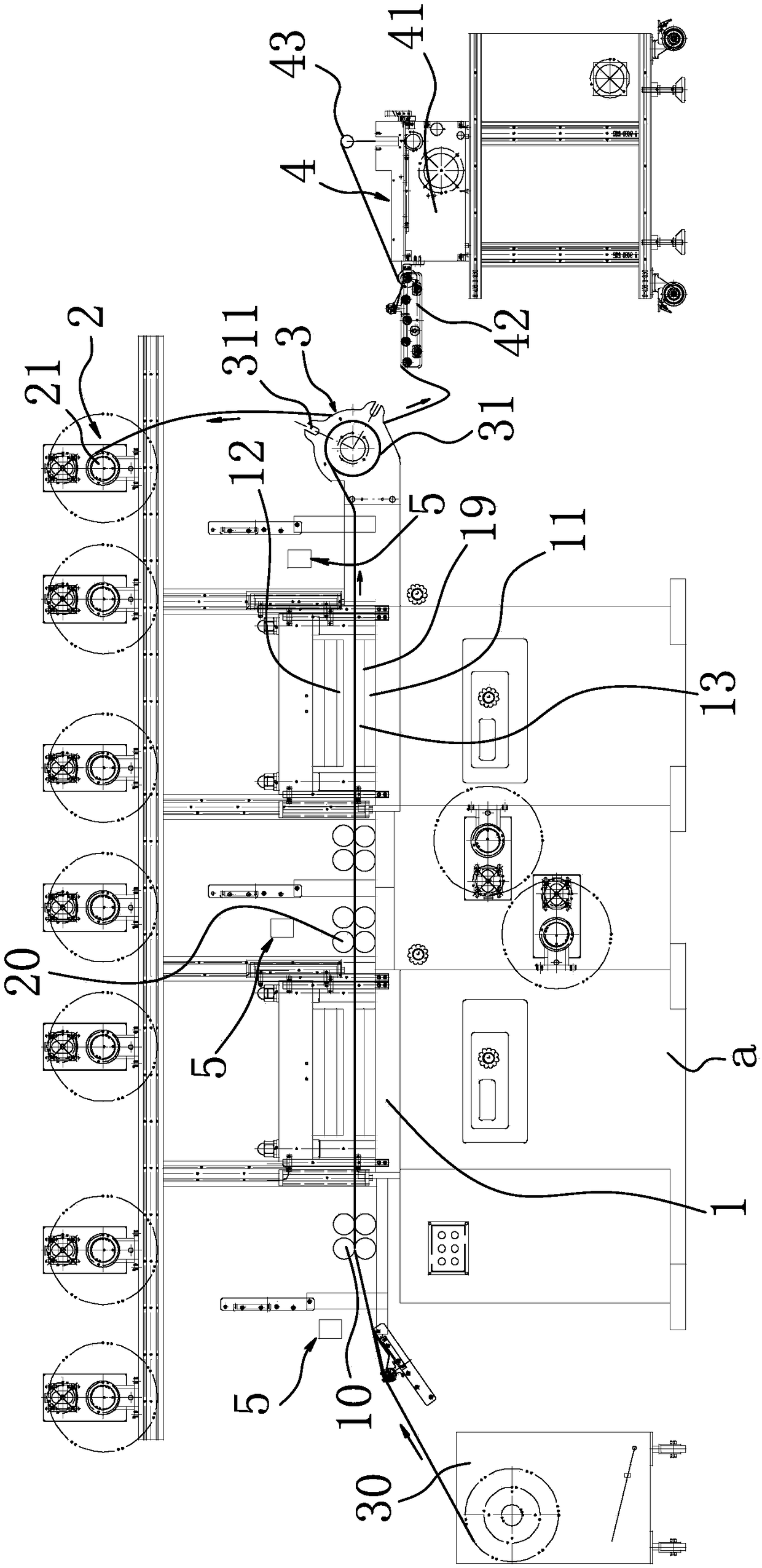
[0071] like Figure 1-5 As shown, the double-station die-cutting equipment for processing and printing label rolls includes a frame a with a conveying platform 1. One end of the conveying platform 1 is the feeding end, and the other end is the discharging end. Unwinding and rewinding device above platform 1.

[0072] Two die-cutting lower dies 11 arranged at intervals are arranged on the conveying platform 1, and two positioning gaps are arranged in the middle of the conveying platform 1, and the die-cutting lower dies 11 are fixed in the positioning gaps one by one.

[0073] There are symmetrically arranged L-shaped briquetting blocks on both sides of the positioning gap, and positioning gaps for pressing the bending part of the...


PUM


Abstract

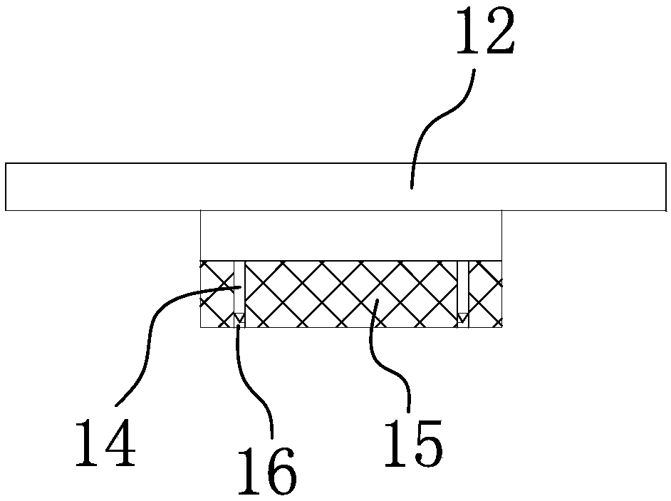
The invention discloses double-station die cutting equipment for machining a printed label roll. The equipment comprises a machine frame with a conveying platform, wherein one end of the conveying platform is a feeding end, the other end of the conveying platform is a discharging end, and the conveying platform is provided with two die cutting lower dies arranged at intervals; a die cutting upperdie is arranged above each die cutting lower die, a hard substrate is arranged on the upper surface of each die cutting lower die, and the upper surfaces of the hard substrates are flush with the upper surface of the conveying platform; annular cutters are arranged in the center areas of the lower surfaces of the die cutting upper dies, flexible buffering pads are further arranged on the lower surfaces of the die cutting upper dies, annular groove bodies for allowing the annular cutters to be inserted are formed in the flexible buffering pads, and the thickness of each flexible buffering pad is larger than the thickness of each annular cutter in the vertical direction; and at least one negative pressure cavity is arranged in the conveying platform, a plurality of vertical adsorption smallholes communicating with the negative pressure cavities are formed in the upper surface of the conveying platform, and a monitoring device used for monitoring the positions of labels on the label rollis arranged on the conveying platform.

Description

technical field [0001] The invention belongs to the technical field of printing label roll production, and in particular relates to a double-station die-cutting device for processing printed label rolls. Background technique [0002] Printed label rolls are generally die-cut in the final process, that is, the excess printed part of the outer circle of the label is removed to achieve the final state desired by the customer. [0003] In order to improve the uniformity of the die-cutting peripheral frame, a cutter is generally used to cut off the printed part during die-cutting, that is, the part on one side of the release paper is cut off more than the printed part. In the process of cutting, the existing cutting tool It is easy to process and cut off the release paper at the same time, which can not meet the production requirements. At the same time, the printed label roll is prone to fluctuate up and down during the conveying process, resulting in a sharp drop in the quality...

Claims


Application Information

Patent Timeline
Patent Type & Authority Applications(China)
IPC IPC(8): B26F1/44B26D3/06B26D7/01
CPCB26D3/06B26D7/01B26D7/015B26D7/018B26F1/44B26F2001/449
Inventor 张海军甄东升
Owner QIANDA NEW MATERIAL CO LTD
Learn More