Refrigerated transport container
A container and box body technology, applied in the field of refrigeration equipment, can solve the problems of extensive transportation organization, increased energy waste, container detention in ports, etc., and achieve the effects of reducing manual participation, improving automation, and reducing monopoly status.
- Summary
- Abstract
- Description
- Claims
- Application Information
AI Technical Summary
Problems solved by technology
Method used
Image

Examples
Embodiment 1
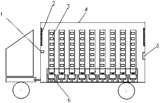
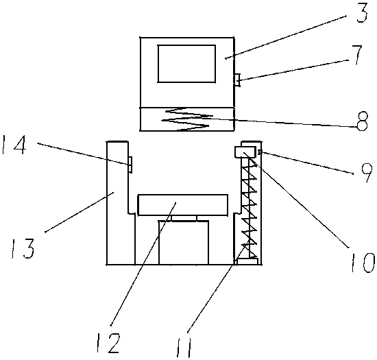
[0023] Such as figure 1 As shown, a refrigerated transport container includes a box body 4, a storage device and a support device 6; the inside of the box body 4 is provided with a temperature sensor 1, a humidity sensor 5 and an air outlet 2; the storage device is composed of multiple A test tube 3 with the same size and shape; the position of the bottom of the test tube 3 body is provided with a fixed block 7; the outside of the bottom of the test tube 3 is provided with a buffer 8; the height of the test tube 3 is smaller than that of the vehicle. The height of the box body 4; the support device 6 includes a position sensor 14, a concave groove 13, a hydraulic device 12, a spring column 11, a movable block 10 and a color sensor 9; the position sensor 14 is located on the left side of the concave groove 13 Above the inner side, the position sensor 14 is spaced from each other when the test tube 3 moves up and down; the body of the test tube 3 is provided with a corresponding...
Embodiment 2
[0026] Such as figure 1 As shown, a refrigerated transport container includes a box body 4, a storage device and a support device 6; the inside of the box body 4 is provided with a temperature sensor 1, a humidity sensor 5 and an air outlet 2; the storage device is composed of multiple A test tube 3 with the same size and shape; the position of the bottom of the test tube 3 body is provided with a fixed block 7; the outside of the bottom of the test tube 3 is provided with a buffer 8; the height of the test tube 3 is smaller than that of the vehicle. The height of the box body 4; the support device 6 includes a position sensor 14, a concave groove 13, a hydraulic device 12, a spring column 11, a movable block 10 and a color sensor 9; the position sensor 14 is located on the left side of the concave groove 13 Above the inner side, the position sensor 14 is spaced from each other when the test tube 3 moves up and down; the body of the test tube 3 is provided with a corresponding...
Embodiment 3
[0029] The third embodiment is basically the same in structure and principle as the first embodiment, except that the hydraulic device 12 is replaced by an electric telescopic rod, which can still achieve the purpose of the present invention.
PUM
 Abstract
Description
Claims
Application Information
 - R&D
- Intellectual Property
- Life Sciences
- Materials
- Tech Scout
- Unparalleled Data Quality
- Higher Quality Content
- 60% Fewer Hallucinations
Browse by: Latest US Patents, China's latest patents, Technical Efficacy Thesaurus, Application Domain, Technology Topic, Popular Technical Reports.
© 2025 PatSnap. All rights reserved.Legal|Privacy policy|Modern Slavery Act Transparency Statement|Sitemap|About US| Contact US: help@patsnap.com