
a drying rack

The technology of a clothes drying rack and a movable plate, which is applied in the field of clothes drying racks, can solve the problems of inconvenience, rainwater is easily blown onto clothes, inconvenient to use, etc., and achieves the effect of simple structure.

Active Publication Date: 2020-02-14
吴芷婧
View PDF5 Cites 0 Cited by
  • Summary
  • Abstract
  • Description
  • Claims
  • Application Information

AI Technical Summary

Problems solved by technology

[0002] The current clothes hanger is basically a simple pole structure or with holes on the pole. It is very inconvenient to put clothes on the clothes hanger and then hang them on the clothes hanger. In different positions on the drying rack, similarly, there is also this problem when collecting clothes, which is very inconvenient, and in rainy weather, especially when accompanied by strong winds, rainwater is easy to be blown onto the clothes, and the clothes have to be collected It's inconvenient to go inside

Method used


Image

  • a drying rack
  • a drying rack
  • a drying rack

Examples


Embodiment Construction

[0032] The following will clearly and completely describe the technical solutions in the embodiments of the present invention with reference to the accompanying drawings in the embodiments of the present invention. Obviously, the described embodiments are only some, not all, embodiments of the present invention.

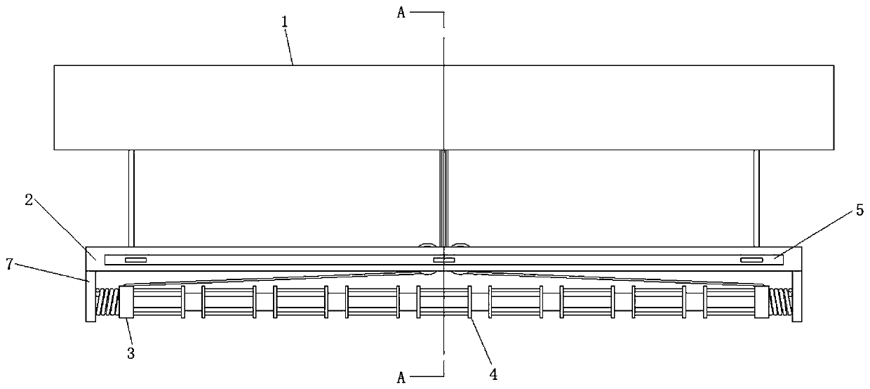
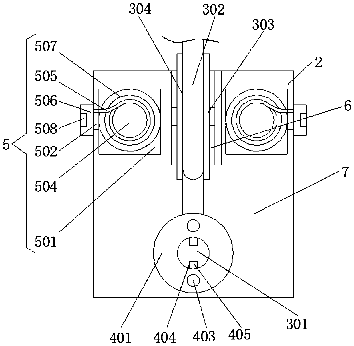
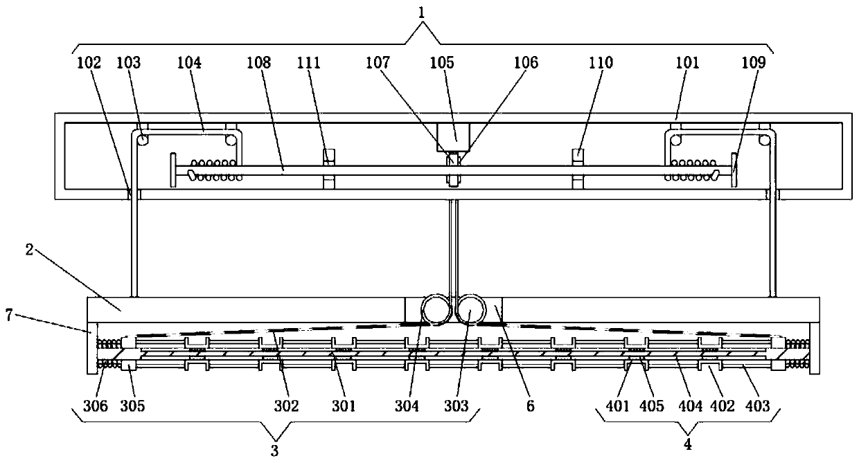
[0033] see Figure 1-4, the present invention provides a technical solution: a clothes hanger, comprising a transmission mechanism 1, a movable plate 2, a recovery mechanism 3, a suspension ring mechanism 4 and a rain-shielding mechanism 5, a through hole 6 is provided in the middle of the movable plate 2, and the movable plate 2 The left and right sides of the lower surface are fixedly connected with connecting plates 7, the transmission mechanism 1 is located above the movable plate 2, and the lower surface of the movable plate 2 is fixedly installed with a recovery mechanism 3 and a ring mechanism 4 between the two connecting plates 7, respectively. The interior o...


PUM


Abstract

The invention discloses a clothes hanger, relating to the technical field of living supplies. The clothes hanger comprises a transmission mechanism, a moving plate, a recovery mechanism, a lifting ring mechanism and a rain shading mechanism, wherein a through hole is formed in the middle of the moving plate, the left side surface and the right side surface of the lower surface of the moving plateare fixedly connected with a connecting plate, the transmission mechanism positioned above the moving plate, the recovery mechanism and the lifting ring mechanism are respectively fixedly arranged onthe lower surface of the moving plate and between the two connecting plates, and the rain shading mechanisms are fixedly arranged inside the moving plate and on the front side and the rear side of thethrough hole. The clothes hanger can realize the ascending and descending operations of the moving plate through the transmission mechanism arranged by utilizing the transmission of a traction motorand a driving rod to drive the driving rod to relax or tighten a connecting rope, and the clothes hanger has a simple structure, and provides a lifting function for the moving plate, thus being helpful to put away or air clothes for a user.

Description

technical field [0001] The invention relates to the technical field of living appliances, in particular to a clothes drying rack. Background technique [0002] The current clothes hanger is basically a simple pole structure or with holes on the pole. It is very inconvenient to put clothes on the clothes hanger and then hang them on the clothes hanger. In different positions on the drying rack, similarly, there is also this problem when collecting clothes, which is very inconvenient, and in rainy weather, especially when accompanied by strong winds, rainwater is easy to be blown onto the clothes, and the clothes have to be collected It is very inconvenient to go to the house. Contents of the invention [0003] (1) Solved technical problems [0004] Aiming at the deficiencies of the prior art, the present invention provides a clothes drying rack, which has the advantages of being convenient for drying and collecting clothes and being able to shield the clothes from rain. ...

Claims


Application Information

Patent Timeline
Patent Type & Authority Patents(China)
IPC IPC(8): D06F57/12
CPCB66D1/7426B66D1/7463B66D1/7484B66D2700/0141D06F57/12
Inventor 吴芷婧
Owner 吴芷婧
Learn More