Bridge height-limitation device convenient to adjust

A technology of height limitation and bridge, which is applied in the direction of bridges, bridge parts, bridge construction, etc., can solve the problems of endangering people's life and property safety, inflexible control, vehicle damage, etc., achieves good shock absorption effect, convenient and fast adjustment, and ensures The effect of shock performance

Inactive Publication Date: 2018-06-29
陈鹏
View PDF6 Cites 2 Cited by
  • Summary
  • Abstract
  • Description
  • Claims
  • Application Information

AI Technical Summary

Problems solved by technology

[0003] Bridge height limit is the main measure to restrict large vehicles from passing through important bridge sections. Every year, important bridges are crushed due to unrestricted large vehicles, and then a lot of money is spent on maintaining bridges, which affects traffic.
Most of the existing bridge viaducts have fixed height-limited beam heights, which restrict the passage of large vehicles and also hinder special vehicles in special periods, such as fire trucks and sprinklers, which cannot be flexibly controlled. In addition, existing bridge viaducts often Will be knocked down by a car, resulting in injury to passers-by, damage to the vehicle, endangering the safety of people's lives and property

Method used


Image

  • Bridge height-limitation device convenient to adjust
  • Bridge height-limitation device convenient to adjust
  • Bridge height-limitation device convenient to adjust

Examples


Embodiment Construction

[0018] The following will clearly and completely describe the technical solutions in the embodiments of the present invention with reference to the accompanying drawings in the embodiments of the present invention. Obviously, the described embodiments are only some, not all, embodiments of the present invention. Based on the embodiments of the present invention, all other embodiments obtained by persons of ordinary skill in the art without making creative efforts belong to the protection scope of the present invention.

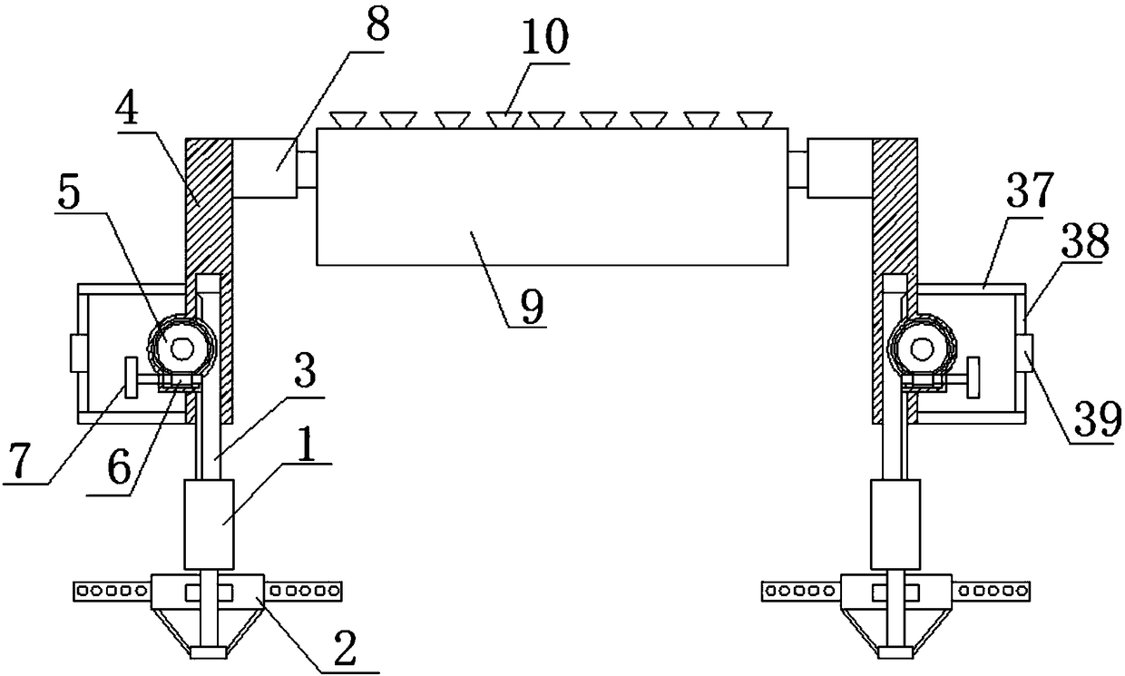
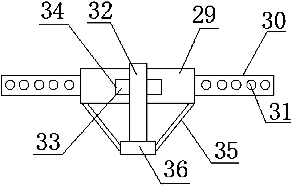
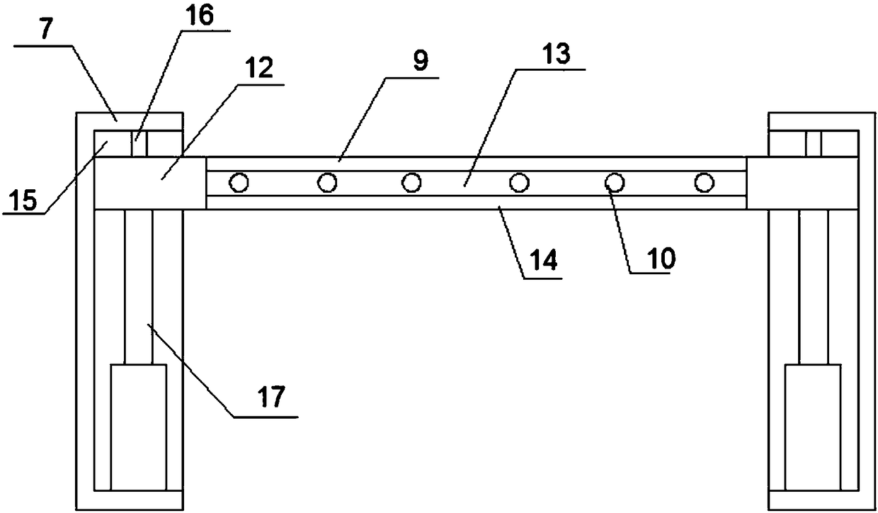
[0019] see Figure 1~4 , in an embodiment of the present invention, a conveniently adjustable bridge height limiting device includes a pillar 1, the lower end of the pillar 1 is provided with a fixing device 2, the fixing device 2 is arranged in the foundation, and the fixing device 2 includes an embedded plate 29 and reinforcing rod 30, the reinforcing rod 30 is provided with the outside of the embedded plate 29, the reinforcing rod 30 is provided with a numb...


PUM


Abstract

The invention discloses a bridge height-limitation device convenient to adjust. The bridge height-limitation device comprises stanchions, fixing devices are arranged at the lower ends of the stanchions, gear shafts are arranged at the upper ends of the stanchions, supporting columns are arranged at the upper portions of the gear shafts, cavities with openings formed in the lower ends are formed inside the supporting columns, the upper ends of the gear shafts are arranged in the cavities, worm wheels matched with the gear shafts are arranged on the outer sides of the supporting columns, worms matched with the worm wheels are arranged on the lower sides of the worm wheels, grooves are formed in the upper sides of supporting frames, sliding grooves are formed in the grooves, sliding blocks are arranged on the sliding grooves, damping devices are arranged between the sliding blocks and the grooves and comprise supporting cylinders and stretchable cylinders, sliding cavities are formed in the cylinder walls of the stretchable cylinders, the upper ends of the supporting cylinders are arranged in the sliding cavities, stanchions are arranged at the lower ends inside the supporting cylinders, stretchable rods are arranged at the upper ends of the stanchions, and damping springs are arranged on the outer sides of the stanchions and the stretchable rods. The bridge height-limitation device is simple in structure and convenient to use, the height is convenient to adjust, the buffering effect is good, and safety is high.

Description

technical field [0001] The invention relates to the technical field of height limiting devices, in particular to a bridge height limiting device with convenient adjustment. Background technique [0002] A bridge (bridge) refers to a building built for roads to cross natural or artificial obstacles. It is erected on rivers, lakes and seas to allow vehicles and pedestrians to pass smoothly. A bridge generally consists of a superstructure, a substructure and ancillary structures. The superstructure mainly refers to the bridge span structure and support system; the substructure includes abutments, piers and foundations; , diversion engineering, etc. According to the structural system of bridges, there are four basic systems: girder bridge, arch bridge, rigid frame bridge, and suspension cable load-bearing (suspension bridge, cable-stayed bridge). [0003] Bridge height limit is the main measure to restrict large vehicles from passing through important bridge sections. Every ye...

Claims


Application Information

Patent Timeline
IPC IPC(8): E01F13/00E01D19/00
CPCE01F13/00E01D19/00
Inventor 陈鹏
Owner 陈鹏
Why Eureka
Try Eureka