
Improved mechanical equipment for indoor building painting

A kind of mechanical equipment, painting technology, applied in the direction of construction, building structure, etc., can solve the problems of poor operation flexibility, large difference in effect, influence, etc., and achieve the effect of simple structure and convenient operation.

Inactive Publication Date: 2018-06-29
韦健杭
View PDF6 Cites 0 Cited by
  • Summary
  • Abstract
  • Description
  • Claims
  • Application Information

AI Technical Summary

Problems solved by technology

[0002] With the acceleration of urbanization, more and more families begin to pay attention to indoor decoration. During the decoration process, the roof and wall surface need to be painted. The existing roller brush needs to be manually held to paint the roller. In the manual operation, auxiliary tools such as ladders or stools are needed for the higher position of the wall. After a long time, it is easy to make people tired, labor-intensive, and very inconvenient. In addition, the dust generated during the manual wall painting process is harmful to the human body Health is affected, the efficiency of manual wall painting is low, and the effect after wall painting is quite different, and the quality of wall painting is uneven
Existing wall brushing mechanical equipment has complex structure, single function, and poor operational flexibility. Therefore, there is an urgent need for a multifunctional brushing device that can meet the needs of roof and wall wall painting.

Method used


Image

  • Improved mechanical equipment for indoor building painting
  • Improved mechanical equipment for indoor building painting
  • Improved mechanical equipment for indoor building painting

Examples


Embodiment Construction

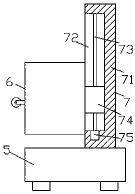
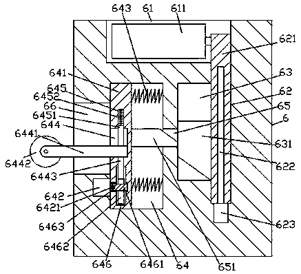
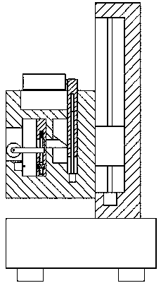
[0015] like figure 1 , figure 2 and image 3 As shown, an improved mechanical equipment for indoor building painting of the present invention includes a loading car body 5, a lifting drive mechanism 7 fixedly installed on the top of the loading car body 5, and a lifting drive mechanism installed on the left side of the lifting drive mechanism 7. The brushing machine body 6 at the end, the top end surface of the brushing machine body 6 is provided with a first accommodating cavity 61, and the inner bottom wall on the right side of the first accommodating cavity 61 is communicated with a first chute 62 extending downwards. A first slide bar 621 extending up and down is connected to the first chute 62 by sliding fit. The side section is provided with a first roller brush 611 that is rotatably connected to the first slide bar 621, and the bottom end surface of the first slide bar 621 is internally threaded and connected with an adjusting screw 622 that extends downward. The ex...


PUM


Abstract

The invention discloses improved mechanical equipment for indoor building painting. The improved mechanical equipment comprises a loading vehicle body, a lifting driving mechanism fixedly mounted on the top of the loading vehicle body and a painting machine body mounted at the left side end of the lifting driving mechanism. A first containing cavity is formed in the top end face of the painting machine body, and a first sliding groove extending downwards is formed in the inner bottom wall of the right side of the first containing cavity in a communicating mode; a first sliding rod extending vertically is connected in the first sliding groove in a sliding fit mode, and the extending tail end of the top of the first sliding rod extends into the first containing cavity; a first roller brush connected with the first sliding rod in a rotating fit mode is arranged in the left side section of the first containing cavity; and an adjusting screw extending downwards is connected in the bottom end face of the first siding rod in a threaded fit mode, and the extending tail end of the bottom of the adjusting screw is connected with an adjusting motor in a power fit mode. The structure is simple, operation is convenient, and automatic adjusting work for different painting demands of the wall surface and the roof wall can be achieved.

Description

technical field [0001] The invention relates to the technical field of architectural decoration, in particular to an improved mechanical equipment for indoor architectural painting. Background technique [0002] With the acceleration of urbanization, more and more families begin to pay attention to indoor decoration. During the decoration process, the roof and wall surface need to be painted. The existing roller brush needs to be manually held to paint the roller. In the manual operation, auxiliary tools such as ladders or stools are needed for the higher position of the wall. After a long time, it is easy to make people tired, labor-intensive, and very inconvenient. In addition, the dust generated during the manual wall painting process is harmful to the human body Health is affected, the efficiency of manual wall painting is low, and the effect after wall painting is quite different, and the quality of wall painting is uneven. Existing wall brushing mechanical equipment h...

Claims


Application Information

Patent Timeline
Patent Type & Authority Applications(China)
IPC IPC(8): E04F21/08
CPCE04F21/08
Inventor 韦健杭
Owner 韦健杭
Learn More