Self-locking chain wheel and self-locking method thereof

A self-locking, sprocket technology, applied in belts/chains/gears, portable lifting devices, rigid shaft couplings, etc., can solve the problems of damaged transmission shafts, difficult disassembly, and inability to disassemble, and achieve load capacity The effect of lifting, adapting to a large range, and reducing stress

Inactive Publication Date: 2018-06-29
宝钢特钢长材有限公司
View PDF2 Cites 3 Cited by
  • Summary
  • Abstract
  • Description
  • Claims
  • Application Information

AI Technical Summary

Problems solved by technology

[0003] 1. Due to the high load characteristics of the sprocket transmission, it is required to adopt overfitting between the inner hole of the sprocket, the keyway and the transmission shaft, so there is a high requirement for the matching size, which brings certain difficulties to the processing and installation. difficulty
[0004] 2. During disassembly, due to the overfitting of the key pins and key grooves, or the "flange" of the key pins, a mechanical card group is formed between the transmission drive shaft and the drive wheel, making disassembly difficult
[0005] 3. In extreme cases, the key pin is deformed and the keyway is damaged, making it impossible to disassemble
Usually, destructive means are used to dismantle, resulting in damage or scrapping of the transmission shaft, and the transmission shaft needs to be reprocessed, causing the equipment to be out of service for a long time

Method used


Image

  • Self-locking chain wheel and self-locking method thereof
  • Self-locking chain wheel and self-locking method thereof
  • Self-locking chain wheel and self-locking method thereof

Examples


Embodiment Construction

[0028] The technical solutions of the present invention will be further described below in conjunction with the accompanying drawings and embodiments.

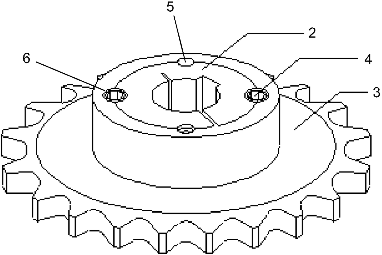
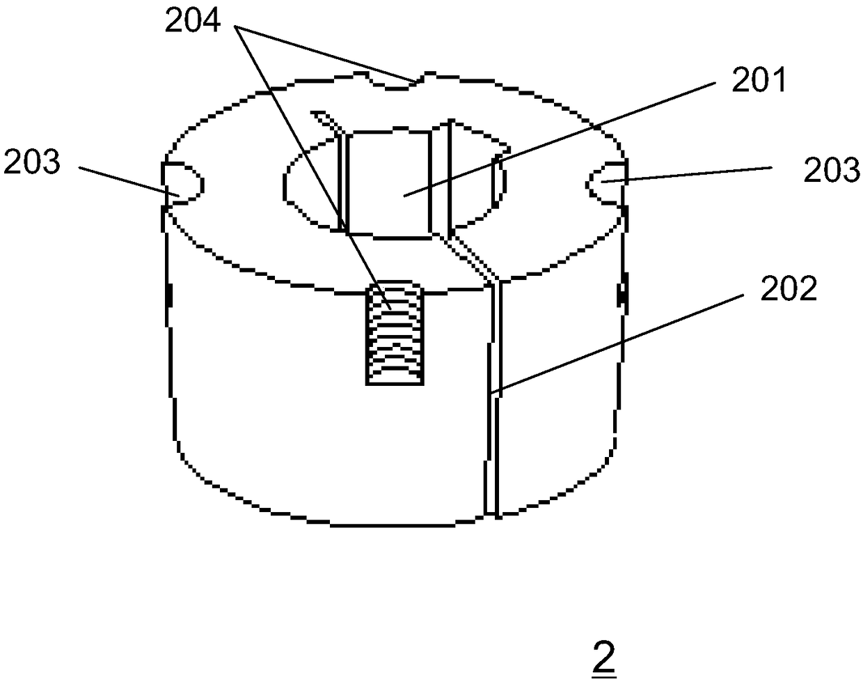
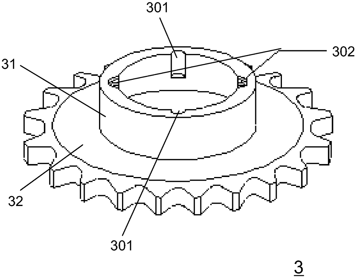
[0029] Please combine Figure 1 to Figure 4 As shown, a self-locking sprocket provided by the present invention is sleeved on the transmission shaft 1, including a locking inner sleeve 2, a gear set 3 and a locking bolt 4, and the locking inner sleeve 2 is set on the gear set 3 and fixed on the transmission shaft 1 through the locking bolt 4.

[0030] Preferably, the outer circle of the locking inner sleeve 2 is set to be a cone, and a through hole 201 is provided on the central line of the transmission shaft. The transmission shaft 1 is arranged in the through hole 201, and the locking inner sleeve 2 There is a gap 202 on the top, which is used to reduce the diameter of the inner circle of the locking inner sleeve 2, and to tighten the locking inner sleeve 2, so that the locking inner sleeve 2 can lock the transmission shaft...


PUM


Abstract

The invention discloses a self-locking chain wheel and a self-locking method thereof. The self-locking chain wheel sleeves a transmission shaft, and comprises a locking inner sleeve, a gear sleeve piece and a locking bolt; and the locking inner sleeve is arranged in the gear sleeve piece, and is fixedly locked on the transmission shaft through the locking bolt. Through coaction between the lockinginner sleeve and the gear sleeve piece, the locking bolt is used for realizing free disassembly of the transmission chain wheel to achieve the purpose of quickly and conveniently mounting and disassembling the chain wheel.

Description

technical field [0001] The invention relates to mechanically manufactured transmission components, more specifically, to a self-locking sprocket and a self-locking method thereof. Background technique [0002] In mechanical equipment, mechanical transmission is a common transmission form, which includes pulley transmission, sprocket transmission, gear transmission and so on. The mechanical transmission is mainly composed of a driving wheel, a driven wheel and an endless belt between the two wheels, a transmission chain or a transmission tooth. And no matter what kind of transmission, the main and slave transmission wheels must be installed and fastened on the transmission transmission shaft, and the power will be transmitted to the target parts through the rotation of the motor transmission transmission shaft. Among the above-mentioned transmission forms, sprocket transmission has the characteristics of large load capacity, less power transmission loss, and low installation...

Claims


Application Information

Patent Timeline
Patent Type & Authority Applications(China)
IPC IPC(8): F16H55/30F16D1/08
CPCF16D1/0829F16D1/0847F16H55/30
Inventor 高翔张伟刚刘向国
Owner 宝钢特钢长材有限公司
Why Eureka
Try Eureka