Fluid control valve

A technology for controlling valves and fluids, applied in valve details, multi-way valves, valve devices, etc., can solve the problems of small air flow, large pressure loss, and large volume of motor control, and achieve on-demand design, small flow loss, The effect of reducing wear

Inactive Publication Date: 2018-06-29
AECC SICHUAN GAS TURBINE RES INST
View PDF4 Cites 4 Cited by
  • Summary
  • Abstract
  • Description
  • Claims
  • Application Information

AI Technical Summary

Problems solved by technology

The existing valves in China mainly include cut-off type, gate type, swing type, spherical type, butterfly type, sliding valve type, roof type and pipe clamp type in structure, and the above valves are more used in civil and industrial fields. , such as water valves, oil valves, low-temperature gas valves, etc., the pressure loss of the existing valves is large when the fluid flows through the control components, and the control is mostly controlled by manual switches or driven by motors. Manual control cannot meet the requirements of the engine. , the motor control is often bulky, there is a limit to the fluid temperature, and it is not suitable for the field of aero-engines
The existing valves on aero-engines are basically aimed at low-temperature fluids, and the controlled air flow is relatively small. At present, there are no relatively mature products for high-temperature fluid control valves.

Method used


Image

  • Fluid control valve
  • Fluid control valve
  • Fluid control valve

Examples


Embodiment Construction

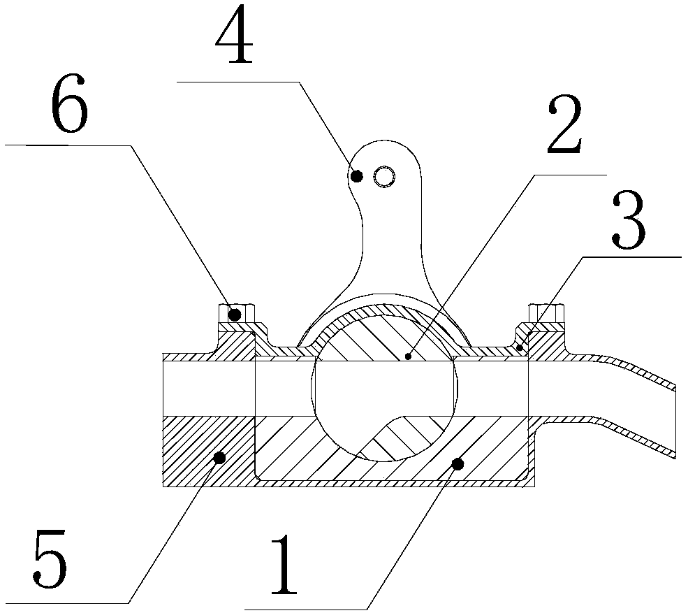
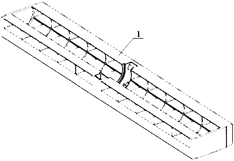
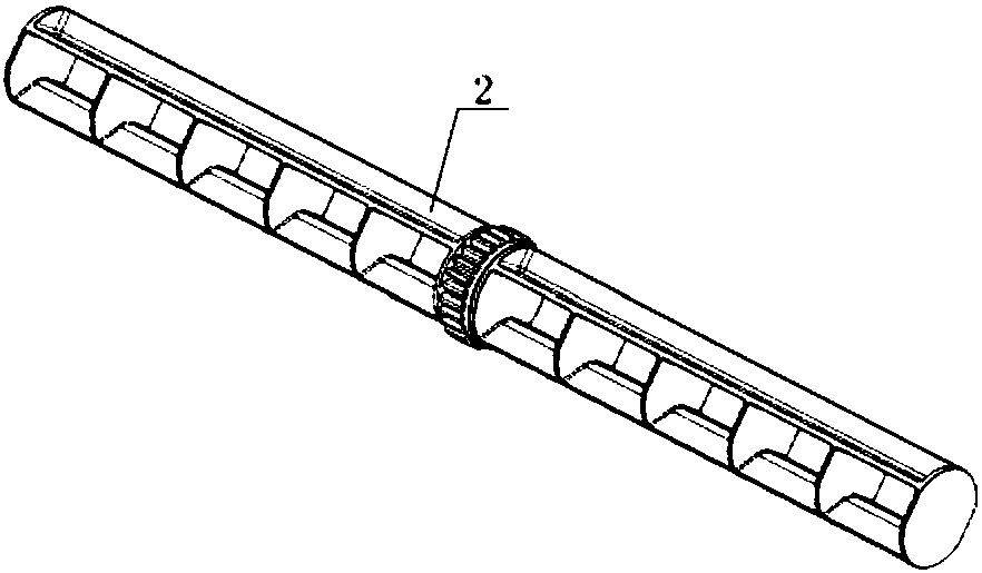
[0031] The structure of the fluid control valve designed by the invention is as figure 1 Shown. The fluid control valve component parts mainly include: a valve body (1); a valve core (2); a cover plate (3); a rocker arm (4); a base (5); a connecting screw (6). The valve body (1), the cover plate (3), and the base (5) are all fixed structures, and the valve core (2) and the rocker arm (4) are rotatable structures.

[0032] In the fluid control valve designed in the present invention, the valve body (1) is provided with a grid-shaped flow channel, such as figure 2 Shown. The basic shape of the outer surface of the valve core (2) is cylindrical, and the valve core (2) is also provided with a grid-like flow channel, such as image 3 As shown, the flow channel passes through the cylindrical surface of the valve core (2), and one end of the flow channel is provided with a guiding angle to reduce flow loss.

[0033] In the fluid control valve designed by the present invention, the rocke...


PUM


Abstract

A fluid control valve comprises a valve body (1), a valve core (2), a cover plate (3) and a rocker arm (4). The valve core (2) is connected with the rocker arm (4) and positioned in the valve body (1), the cover plate (3) covers the valve core (2), and the rocker arm (4) is driven by external force to drive the valve core (2) to rotate so as to control flow passage connection and disconnection. Control of fluid connection and disconnection and two flow directions can be realized according to requirements by the fluid control valve. The fluid control valve has advantages of small size, low airflow loss, realization of noncontact seal, applicability to high-temperature fluid and the like, different flow rate requirements can be met conveniently through structural size parameter modificationaccording to different flow area demands, and accordingly design as required can be realized.

Description

Technical field [0001] The invention belongs to the field of fluid control and relates to a fluid control valve. Background technique [0002] On the hot-end components of the aero-engine, the high-temperature secondary flow is flow controlled to realize the on-off and direction control of the secondary flow path, which requires the use of high-temperature gas control valves. The existing domestic valves mainly include cut-gate, gate, swing, spherical, butterfly, slide valve, roof and pipe clamp types in structure. The above-mentioned valves are more used in civil and industrial fields. , Such as water valve, oil valve, low-temperature air valve, etc., the existing valve has a large pressure loss when the fluid flows through the control element. In the control, manual switch control is used or the switch is driven by a motor. The manual control cannot meet the requirements of the engine. , The motor control is often bulky, has limitations on fluid temperature, and is not suitabl...

Claims


Application Information

Patent Timeline
Patent Type & Authority Applications(China)
IPC IPC(8): F16K5/04F16K11/085F16K27/06
CPCF16K5/0407F16K11/0853F16K27/065
Inventor 罗斌廖华琳郭建伟黄顺洲朱川马钊罗红飞
Owner AECC SICHUAN GAS TURBINE RES INST
Why Eureka
Try Eureka