Micro-liquid-flow electromagnetic commutator

A technology of liquid flow and electromagnetic commutation, which is applied in the calibration of small liquid flow, small liquid flow electromagnetic commutator, and commutation during detection. It can solve the problems of inapplicable small liquid flow, high space and site requirements, and large volume of pneumatic commutators, and achieve the effects of short action time, low environmental requirements, and convenient installation and disassembly.

Pending Publication Date: 2018-06-29
WUHAN INST OF MEASUREMENT & TESTING TECH
View PDF0 Cites 3 Cited by
  • Summary
  • Abstract
  • Description
  • Claims
  • Application Information

AI Technical Summary

Problems solved by technology

[0002] Most of the current liquid flow standard devices are fixed and have a large flow rate. Most of the commutators used for the fluid reversing of the large-flow fixed liquid flow standard devices are pneumatic commutators, and the pneumatic commutators are generally large in size. The structure is complex, and the pneumatic system is mostly composed of air compressors, gas storage tanks and many pipelines. It has high requirements for space and site, and cannot be moved at will. It is not suitable for the reversing of small liquid flow and the needs of on-site testing.

Method used


Image

  • Micro-liquid-flow electromagnetic commutator
  • Micro-liquid-flow electromagnetic commutator
  • Micro-liquid-flow electromagnetic commutator

Examples


Embodiment Construction

[0031] In order to make the technical means, creative features, goals and effects achieved by the present invention easy to understand, the following will further explain how the present invention is implemented in conjunction with the accompanying drawings and specific implementation methods.

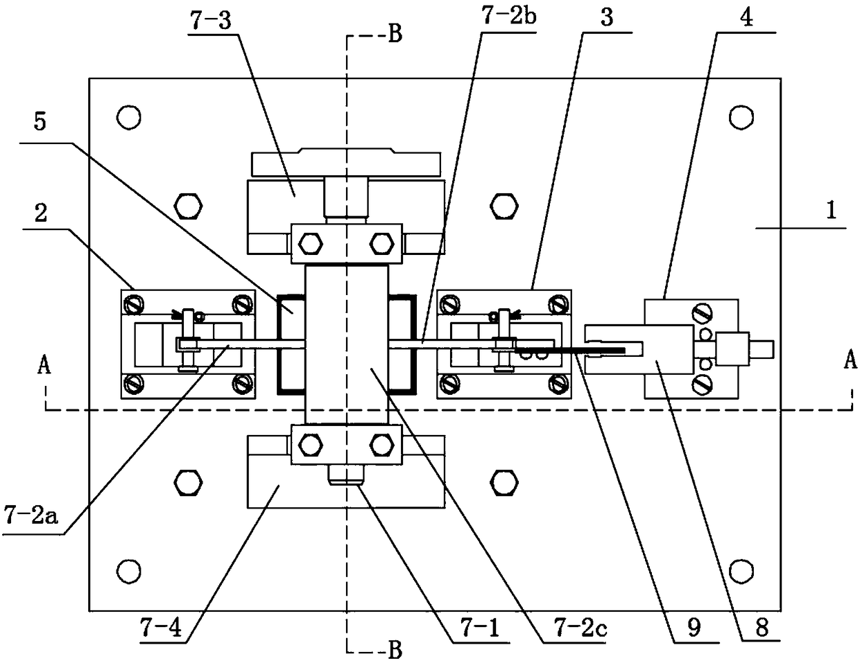
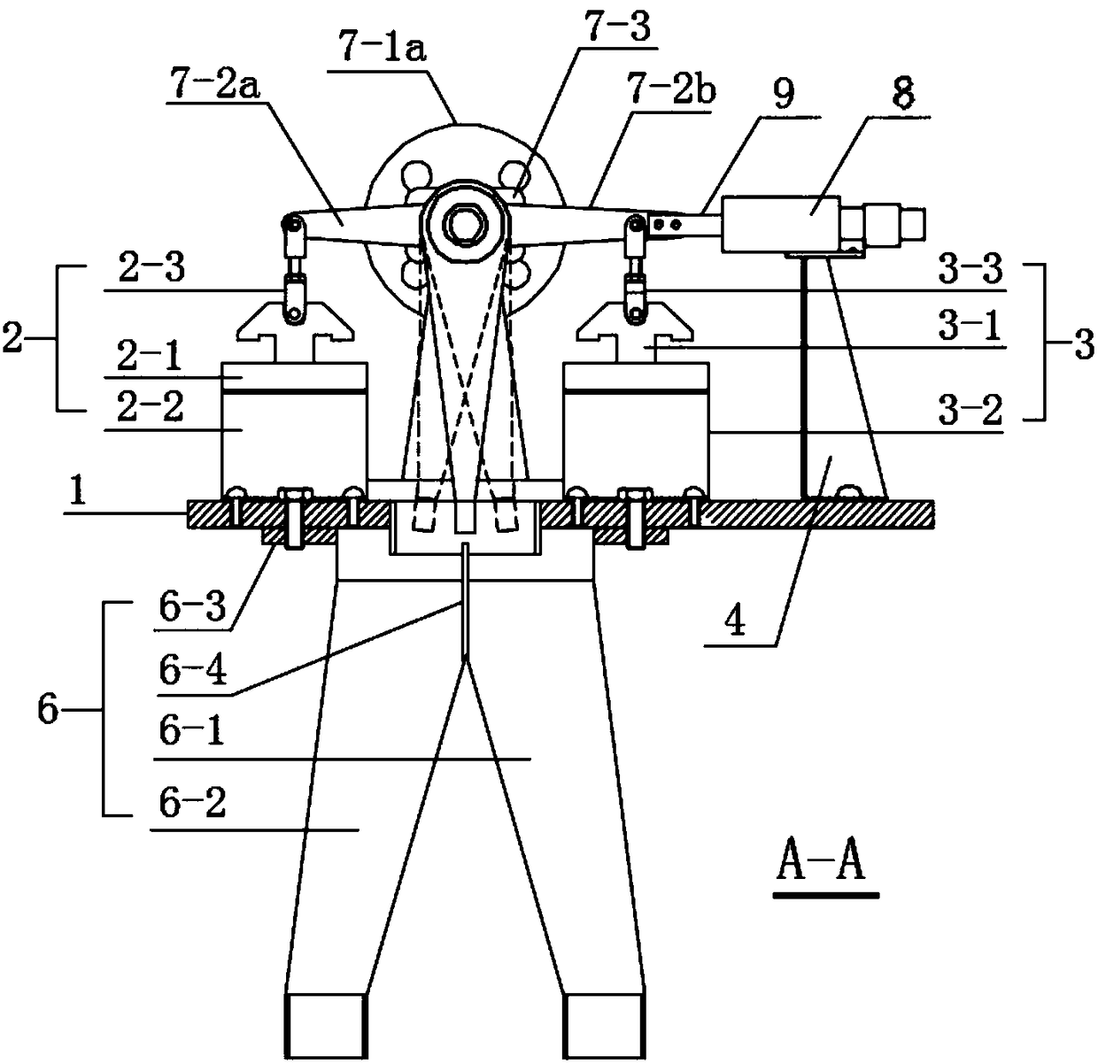
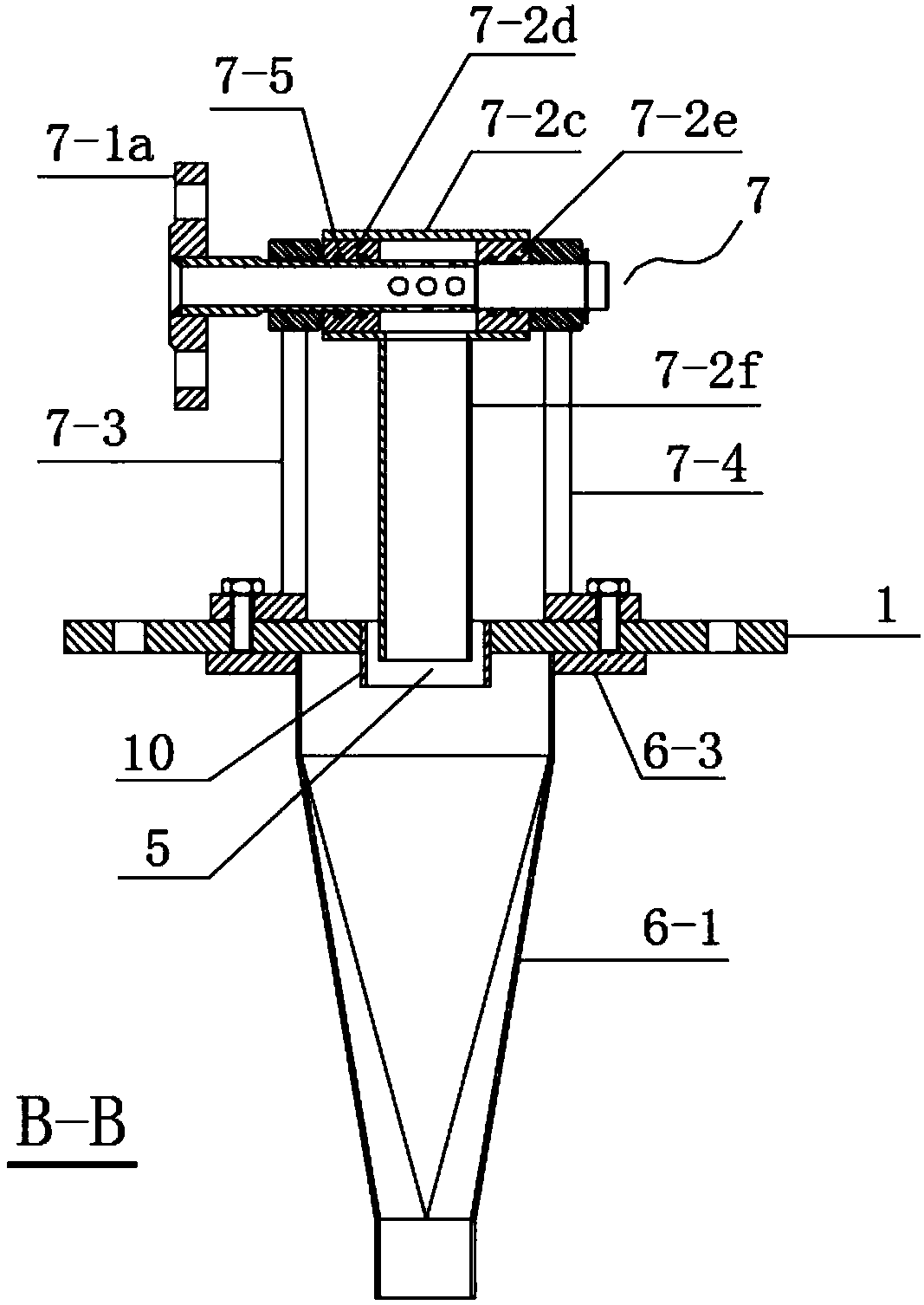
[0032] Such as Figure 1 to Figure 3 As shown, a tiny liquid flow electromagnetic commutator provided by the present invention includes a bottom plate 1, and a left traction electromagnet 2, a right traction electromagnet 3 and a transmitter bracket 4 are sequentially arranged on the top of the bottom plate 1 from left to right, Between the left traction electromagnet 2 and the right traction electromagnet 3 and on the bottom plate 1, there is a water inlet 5 for drainage, and a pants-type liquid diversion device 6 is provided directly below the water inlet 5. In the water inlet A liquid drainage device 7 is provided directly above the 5, and a photoelectric pulse transmitter 8 is prov...


PUM


Abstract

The invention discloses a micro-liquid-flow electromagnetic commutator which comprises a bottom plate. The micro-liquid-flow electromagnetic commutator is characterized in that a left traction electromagnet, a right traction electromagnet and a communicator support are sequentially arranged on the upper portion of a base plate from left to right, the bottom plate is provided with a water inlet hole between the left and right traction electromagnets, a branched liquid distribution device and a liquid guide device are arranged above and under the water inlet hole respectively and both communicated with the water inlet hole, and a photoelectric pulse communicator is arranged on the communicator support. By coil power on-off control of the left and right traction electromagnets, commutation ofthe electromagnetic commutator is realized; in a commutation process, the photoelectric pulse communicator is triggered by a light barrier to record commutation actuation time nodes. The micro-liquid-flow electromagnetic commutator has advantages of small size, portability, convenience and quickness in mounting and demounting, structural steadiness, shock resistance, impact resistance, quicknessin commutation action, movability and low environmental requirements of places, energy supply and the like.

Description

technical field [0001] The invention relates to the technical field of flow detection equipment, in particular to an electromagnetic commutator for micro liquid flow, which is mainly used for micro liquid flow calibration and commutation during detection. Background technique [0002] Most of the current liquid flow standard devices are fixed and have a large flow rate. Most of the commutators used for the fluid reversing of the large-flow fixed liquid flow standard devices are pneumatic commutators, and the pneumatic commutators are generally large in size. The structure is complex, and the pneumatic system is mostly composed of air compressors, gas storage tanks and many pipelines. It has high requirements for space and site, and cannot be moved at will. It is not suitable for the reversing of small liquid flow and the needs of on-site testing. Contents of the invention [0003] The object of the present invention is to provide an electromagnetic commutator for small liq...

Claims


Application Information

Patent Timeline
Patent Type & Authority Applications(China)
IPC IPC(8): G01F25/00
CPCG01F25/10
Inventor 洪传文檀臻许建平郭均瑶张民
Owner WUHAN INST OF MEASUREMENT & TESTING TECH
Why Eureka
Try Eureka