Overlaying-ring ring shear apparatus as well as overlaying ring shear test

A ring shearing instrument and ring-type technology, applied in the field of geotechnical testing technology and deformation simulation, can solve the problems of strength parameter gap, influence of experimental results, influence of uneven material, etc. The effect of reducing running resistance

Pending Publication Date: 2018-06-29
FUJIAN GEOLOGICAL ENG SURVEY INST
View PDF8 Cites 20 Cited by
  • Summary
  • Abstract
  • Description
  • Claims
  • Application Information

AI Technical Summary

Problems solved by technology

Although the direct shear test is simple to operate, it also has obvious disadvantages: 1. The direct shear test uses a fixed shear surface, but most objects have elastic deformation and plastic deformation before and after failure, and the shear strain concentration area and deformation damage area should be It is in the shape of a band instead of a plane, and there is a gap between the strength parameters obtained by using the fixed shear surface and the actual situation; Influenced by inhomogeneous materials such as nearby hard blocks and defects; 3. During the shearing process, due to the staggering of the upper and lower samples, the shear area changes, which affects the experimental results; 4. The direct shear test has a small shear distance and cannot be completed large displacement shear
Although the triaxial test provides a certain degree of freedom for the width and position of the shear plane, it also has the problem of being easily affected by inhomogeneous substances such as hard blocks and defects near the shear plane, and the shear distance is small
However, since it still uses a single shear plane, the result is still the sliding friction of a single interface, which cannot consider other deformation states and displacements of other potential shear planes during the shear deformation process, and the uniformity of the sample still remains more sensitive

Method used


Image

  • Overlaying-ring ring shear apparatus as well as overlaying ring shear test
  • Overlaying-ring ring shear apparatus as well as overlaying ring shear test
  • Overlaying-ring ring shear apparatus as well as overlaying ring shear test

Examples


example 1

[0081] Example 1: Traditional Ring Shear Test

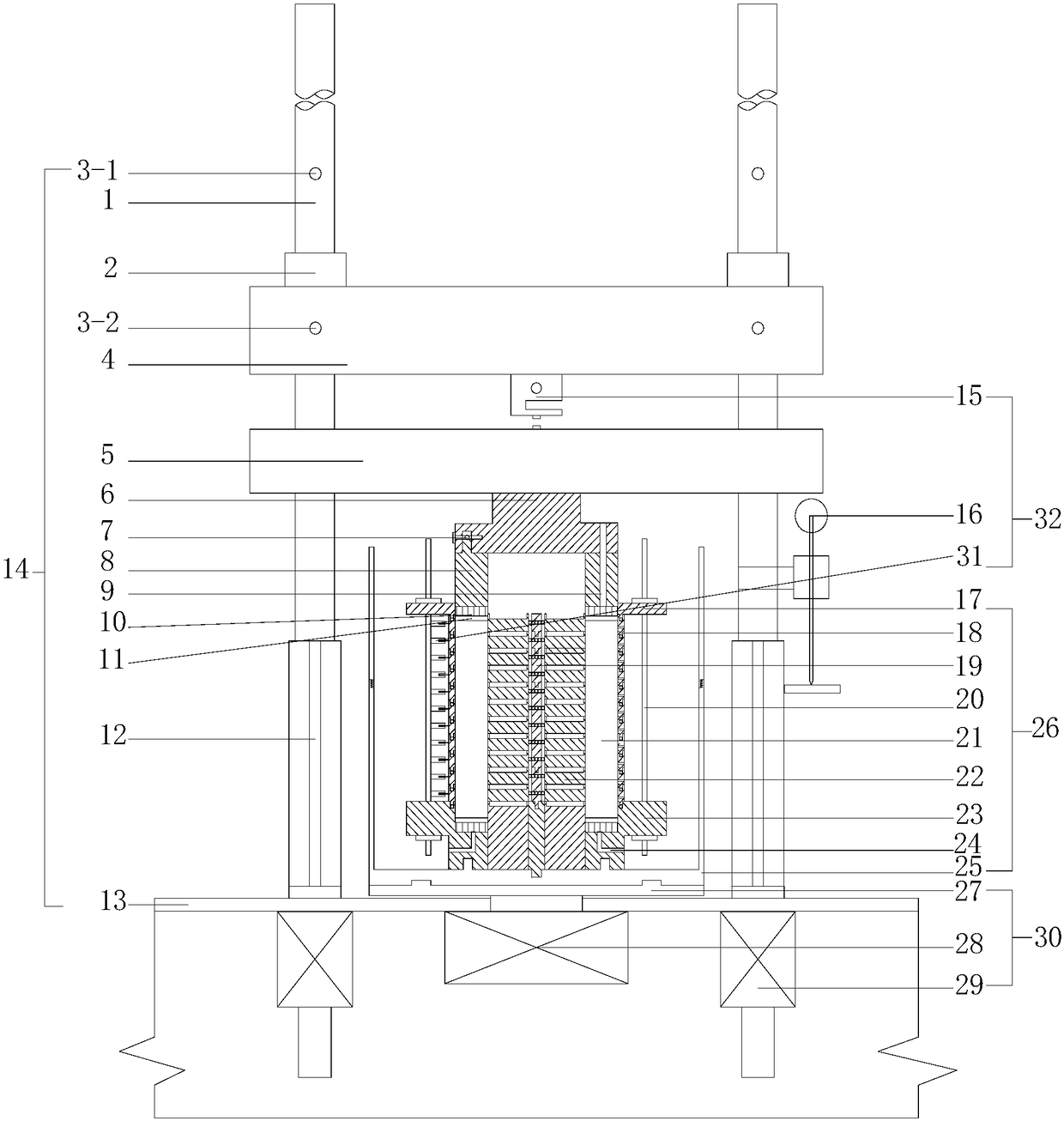
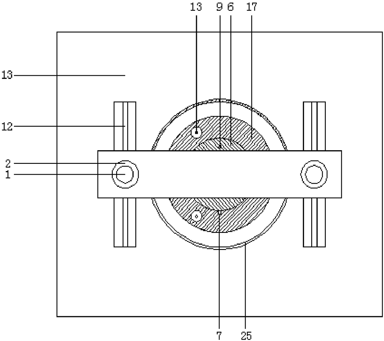
[0082] (1) Sample preparation: The annular soil sample (sample) is prepared by a traditional sample preparation device, and loaded into the lower shear box 23 . Keep a movable wall ring and a lamination, insert the central axis 19 of a lamination height into the bottom groove of the water bath box 25 and fix it, and put the collar 17 on it. A shorter shear box bracket 20 is selected for fixing, and the stacked ring shear box and the water bath box 25 are placed on the drive plate 27 to complete the sample preparation.

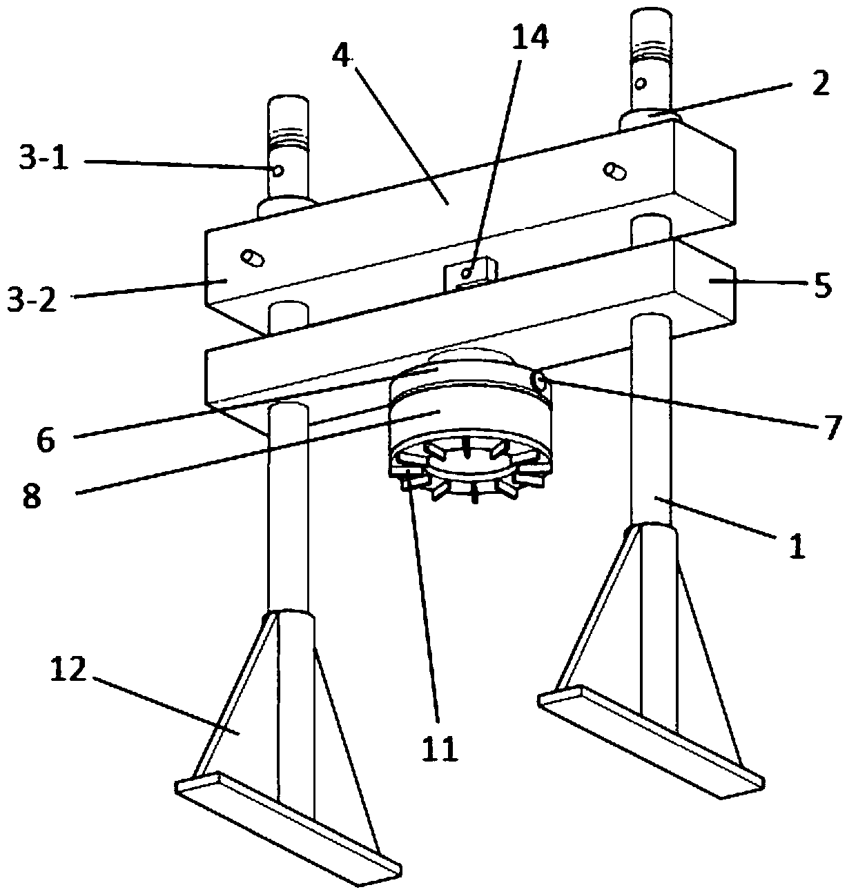
[0083] (2) Equipment debugging: Fix the fixed beam 4 to the position of the lowermost pin hole 3-1 on the column 1, and lock the locking nut. Push the movable beam 5 to the lower part until it contacts the upper surface of the sample.

[0084] (3) Consolidation: Start the vertical pressurization motor 29 to move the fixed beam 4 downward, make the stress gauge 15 contact the movable beam 5, and apply vertical pr...

example 2

[0086] Example 2: stacked ring shear test

[0087] (1) Sample preparation: For undisturbed soil samples, the method of filling layer by layer can be used for sample loading; for undisturbed soil samples, a special in-situ sampler can be used for soil sample collection and filling, and the final soil sample height should be less than the movable wall ring Group 18 and lamination group 22 are of the same height. After the soil sample is filled to the preset height, the upper collar 17 is covered and locked by the shear box bracket 20, and the stacked ring shear box and water bath box that have completed the sample loading are placed on the drive plate 27 and fixed, and the sample loading is completed ;

[0088] (2) Equipment debugging: Adjust the height of the fixed beam 4 and the water bath box 25 according to the height of the sample. Generally, the height of the fixed beam 4 and the height of the water bath box 25 are based on the fact that the movable beam 5 is not in cont...

example 3

[0091] Example 3: Simulation test of complex soil deformation

[0092] (1) Sample preparation: If the undisturbed soil sample is selected, a special in-situ sampler can be used to collect and fill the soil sample, or the model test soil sample can be stacked after scaled down according to the actual stratum conditions. After the soil sample is filled to the preset height, the upper collar 17 is covered and locked by the shear box bracket 20 to complete the sample loading;

[0093] (2) Equipment debugging and consolidation: The equipment adjustment and consolidation methods are the same as in Example 2.

[0094](3) Ring shear: After the consolidation is completed, install a displacement monitoring instrument to ensure that the instrument probes are in contact with the movable wall ring and the column support 12 respectively, insert steel nails into the through holes of the movable wall ring, and open it under the condition of maintaining vertical pressure Twist the motor 28 to...


PUM


Abstract

The invention belongs to the field of geotechnical test and deformation simulation, and particularly relates to an overlaying-ring ring shear apparatus and an overlaying ring shear test for continuouslarge-displacement shear deformation characteristic research of soil and complicated structural soil deformation simulation. The overlaying-ring ring shear apparatus comprises a vertical pressurizingmechanism, a twisting mechanism, a vertical assisting pressure applying mechanism and an overlaying ring shear box mechanism; the overlaying ring shear box mechanism is arranged on the twisting mechanism and can be driven by the twisting mechanism to rotate; the vertical pressurizing mechanism can apply vertical pressure to the overlaying ring shear box mechanism by virtue of the vertical assisting pressure applying mechanism; the limitless deformation ring-shaped shear of different geotechnical test samples of different heights can be performed, and the test sample is enabled to have certainfreedom and continuity in the deformation process; and the overlaying-ring ring shear apparatus can also be used for researching a deformation law of different material contact surfaces, simulating long-distance deformation of the complicated structural soil landslide as well as searching soft layers.

Description

technical field [0001] The invention belongs to the field of rock and soil testing technology and deformation simulation, and is especially used for the research on the characteristics of continuous large-displacement shear deformation of soil and the simulation of soil deformation of complex structures, specifically a stacked ring type ring shear instrument and a stacked type ring shear test. Background technique [0002] The natural soil structure is complex, and there are various shear deformation processes under the same complex stress. For example, it can form a band-shaped plastic deformation, or form a nearly planar rigid slip on a certain weak surface, and more fragmentary The rolling deformation of the stone formed near the shear zone. In addition, the morphology and intensity characteristics of shear bands are more complex if temporal and spatial dimensions are considered. The complex nature of the soil makes it impossible for the general mechanical model to expla...

Claims


Application Information

Patent Timeline
Patent Type & Authority Applications(China)
IPC IPC(8): G01N3/24
CPCG01N3/24G01N2203/0682G01N2203/0676G01N2203/0025G01N2203/005
Inventor 陈志超柳侃叶龙珍张智超
Owner FUJIAN GEOLOGICAL ENG SURVEY INST
Why Eureka
Try Eureka