Hydraulic chuck for diehead threading machine

A technology of hydraulic chuck and threading machine, which is applied in the direction of clamping, metal processing machinery parts, support, etc., can solve problems such as clamp marks, achieve good force effect and facilitate reciprocating action

Pending Publication Date: 2018-07-03
CEC JINJIANG INFO IND
View PDF6 Cites 5 Cited by
  • Summary
  • Abstract
  • Description
  • Claims
  • Application Information

AI Technical Summary

Problems solved by technology

[0002] At present, threading machines generally use manual impact three-jaw chucks, which use dovetail-shaped small claws at the contact with the steel pipe surface, which can easily clamp the steel pipe with little force, but the small claws will form a clamp on the steel pipe surface. There is nothing that can be done to the piping system that does not allow damage to the surface of the steel pipe

Method used


Image

  • Hydraulic chuck for diehead threading machine
  • Hydraulic chuck for diehead threading machine

Examples


Embodiment Construction

[0023] The present invention will be further described below in conjunction with the accompanying drawings, but the protection scope of the present invention is not limited to the following description.

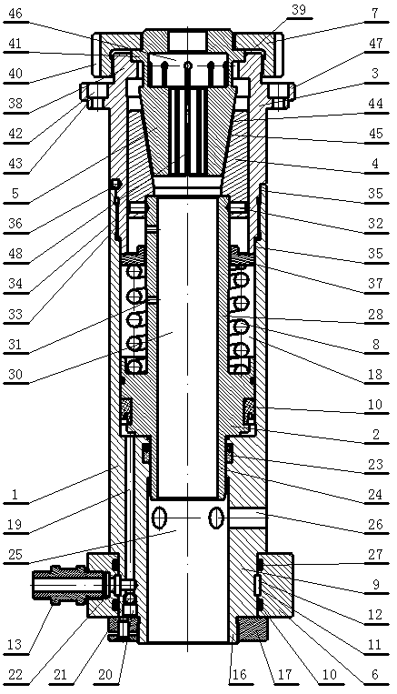
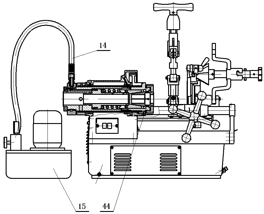
[0024] Such as figure 1 and figure 2 As shown, the hydraulic chuck for threading machine includes cylinder 1, piston 2, front sleeve 3, taper sleeve 4, jacket 5, sliding sleeve 6, pressure ring 7 and spring 8, and the cylinder cavity in cylinder 1 includes the upper The large cavity 18 and the small cavity 25 at the lower part, the large cavity 18 and the small cavity 25 are connected in a stepped shape, the piston 2 is placed in the cylinder cavity, the large cavity 18 is connected with the front sleeve 3, and the front sleeve 3 is equipped with a taper sleeve 4, The lower end of the taper sleeve 4 is against the piston 2, and there is a taper hole 44 in the taper sleeve 4, and the jacket 5 is installed in the taper hole 44, and the jacket 5 is locked on the front sleeve 3...


PUM


Abstract

The invention relates to a hydraulic chuck for a diehead threading machine. The hydraulic chuck for the diehead threading machine comprises an oil cylinder, a piston, a front sleeve, a taper sleeve, ajacket, a slide sleeve, a pressing ring and a spring; an oil cylinder cavity in the oil cylinder comprises a large cavity at the upper part and a small cavity at the lower part; the large cavity andthe small cavity communicate to form a step form; the piston is placed in the oil cylinder cavity; the front sleeve is arranged in a cavity mouth of the large cavity; the taper sleeve is mounted in the front sleeve; the lower end of the taper sleeve butts against the piston; a conical hole is formed in the taper sleeve; the jacket is mounted in the conical hole, and is locked on the front sleeve through the pressing ring; the spring sleeves the piston; the lower end of the spring butts against a projection at the middle lower part of the piston; the upper end of the spring butts against an annular baffle plate; the annular baffle plate butts against the end surface of the front sleeve; the slide sleeve is arranged on the outer surface of the oil cylinder in the small cavity; an oil nozzleis mounted on the slide sleeve; and the oil nozzle is connected with a pump station through a high-pressure oil pipe. The hydraulic chuck for the diehead threading machine has the beneficial effects of no deformation of steel pipes, high tightening strength and good tightening effect.

Description

technical field [0001] The invention relates to the field of hydraulic chucks, in particular to the hydraulic chucks for threading machines. Background technique [0002] At present, threading machines generally use manual impact three-jaw chucks, which use dovetail-shaped small claws at the contact with the steel pipe surface, which can easily clamp the steel pipe with little force, but the small claws will form a clamp on the steel pipe surface. If there are no traces, there is nothing that can be done to the piping system that does not allow damage to the surface requirements of the steel pipe. Especially in recent years, with the appearance of plastic-coated steel pipes on the surface, the requirement for not allowing damage to the coated surface of steel pipes is even more urgent. Contents of the invention [0003] The object of the present invention is to overcome the disadvantages of the prior art and provide a hydraulic chuck for a threading machine with no deform...

Claims


Application Information

Patent Timeline
Patent Type & Authority Applications(China)
IPC IPC(8): B23Q3/08
CPCB23Q3/082
Inventor 赫荣嘉钟传文
Owner CEC JINJIANG INFO IND
Why Eureka
Try Eureka