Bi-directional doctor blade unit for textile printing machines

A technology of scraper device and printing machine, which is applied to the configuration of textile material equipment, printing machines, rotary printing machines, etc. It can solve the problems of uneven scraping liquid, residual liquid flow, and wear of the roller surface, so as to achieve ink scraping or scraping Uniform, smooth liquid circulation, stable color and hue effect

Active Publication Date: 2020-04-21
NEWTECH TEXTILE TECH DEV SHANGHAI
View PDF7 Cites 0 Cited by
  • Summary
  • Abstract
  • Description
  • Claims
  • Application Information

AI Technical Summary

Problems solved by technology

[0004] The traditional inking or sizing device with an open single scraper has problems such as uneven scraping liquid, liquid accumulation between the scraper and the roller, and residual liquid flow.
[0005] In addition, since the liquid tank is open, it also has the following defects: 1) The liquid in the liquid tank has a large amount of volatilization, and the air flow around the printing unit will be accelerated by the exhaust fan, so that the liquid is easy to deposit and cannot be transferred smoothly to the printing material; 2) A large amount of liquid volatilizes, and if it is not replenished in time, the viscosity of the liquid will be changed; 3) The liquid is easily affected by the ambient temperature, which makes the printing quality not stable enough
[0006] Moreover, prior art doctor blade devices do not allow fine adjustment of the contact pressure between the doctor blade and the roller
Therefore, on the one hand, the quality of the liquid supply may be low due to too small contact pressure, and on the other hand, the surface of the roller may be worn due to excessive contact pressure.

Method used


Image

  • Bi-directional doctor blade unit for textile printing machines
  • Bi-directional doctor blade unit for textile printing machines
  • Bi-directional doctor blade unit for textile printing machines

Examples


Embodiment Construction

[0034] The technical solution of the present invention will be described in further detail below with reference to the accompanying drawings and the enumerated implementation manners. It should be noted that any technical features and any technical solutions in this embodiment do not limit the protection scope of the present invention, and the protection scope of the present invention should include any equivalent or replacement technology that can be imagined by those skilled in the art without creative efforts Program.

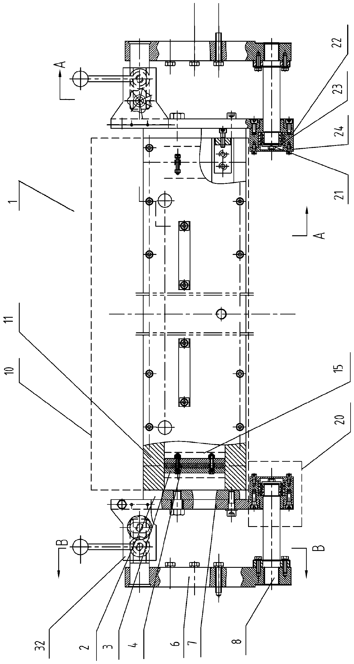
[0035] In this manual, refer to figure 1 , the longitudinal direction refers to the direction extending along the axial direction of the printing plate roll, and the transverse direction refers to the direction perpendicular to the longitudinal direction and located at figure 1 By a direction in the plane of the paper, a lateral direction refers to a direction perpendicular to the longitudinal direction and the transverse direction. In addition, the upper ...


PUM


Abstract

A bi-directional scraper apparatus (1) for a textile printing machine, the bi-directional scraper apparatus (1) comprising: a scraper assembly (10), the scraper assembly (10) comprising a scraper holder (11), two scrapers (12), and corresponding scrapper pressing plates (13), the scraper holder (11) having a groove (14), the two scrapers (12) being obliquely mounted, with their blades opposing each other, on either side of an opening of the groove (14) and extending along a vertical direction, the scraper pressing plates (13) being used for tightly pressing the scrapers (12) onto the scraper holder (13); end seal parts (15) used for sealing the two vertical ends of the scraper assembly (10); a displacement mechanism (20) used for making the scraper assembly (10) to pivotally move between a working position and a non-working position, the displacement mechanism (20) having a pivot part; and an adjustment mechanism (30) used for adjusting a contact pressure between the scrapers (12) and a roller when the scraper assembly (10) is at the working position. Also provided is a textile printing machine comprising the bi-directional scraper apparatus (1).

Description

technical field [0001] The invention relates to a bidirectional scraper device for a textile printing machine. The invention also relates to a textile printing machine comprising said bidirectional doctor device. Background technique [0002] There are many types of printing and dyeing techniques and machinery, and a wide range of products. At present, the main printing processes include screen printing, roller printing, platen printing, transfer printing and digital inkjet printing, etc., and the corresponding equipment is mainly rotary screen printing machine, flat screen printing machine, roller printing machine, platen Printing machine, transfer printing machine, digital inkjet printing machine, etc. [0003] Printing machines usually include an inking or sizing device for inking or sizing the printing plate roll or coating roll (or anilox roll). Traditional inking or sizing devices usually include rollers, scrapers and tanks, etc. The lower semicircle of the roller ...

Claims


Application Information

Patent Timeline
Patent Type & Authority Patents(China)
IPC IPC(8): B41F9/10
CPCB41F9/1081B41F9/10B41F35/04D06B23/20
Inventor 钟博文
Owner NEWTECH TEXTILE TECH DEV SHANGHAI
Why Eureka
Try Eureka