
Racing traversing exercise machine for unmanned aerial vehicle

A technology for training aircraft and aircraft racing, applied in the field of unmanned aerial vehicles, it can solve problems such as poor control of the center of gravity, damage, and plane crashes, to enhance stability and reliability, facilitate installation and disassembly, and reduce technological processes. Effect

Pending Publication Date: 2018-07-06
TIANJIN SINO GERMAN VOCATIONAL TECHNICAL COLLEGE
View PDF0 Cites 4 Cited by
  • Summary
  • Abstract
  • Description
  • Claims
  • Application Information

AI Technical Summary

Problems solved by technology

The traditional traversal frame is composed of straight arms and carbon fiber four-axis multilateral center plate. The disadvantages are that the stability is not enough, the center of gravity is not well controlled, which is not conducive to the protection of the battery and flight control, and the battery will touch the ground when placed to cause friction. Damage, after a collision will cause the flight control and key components to temporarily fail
During flight racing, the movement of multi-rotors depends on the speed change and torque adjustment of the propellers. The leakage of the propeller blades will easily lead to flight safety and cause the plane to crash.
Moreover, the reliability of the mechanical structure of the multi-rotor is low, and there are no movable parts in the mechanism, which is prone to wear and tear during flight

Method used


Image

  • Racing traversing exercise machine for unmanned aerial vehicle
  • Racing traversing exercise machine for unmanned aerial vehicle
  • Racing traversing exercise machine for unmanned aerial vehicle

Examples


Embodiment Construction

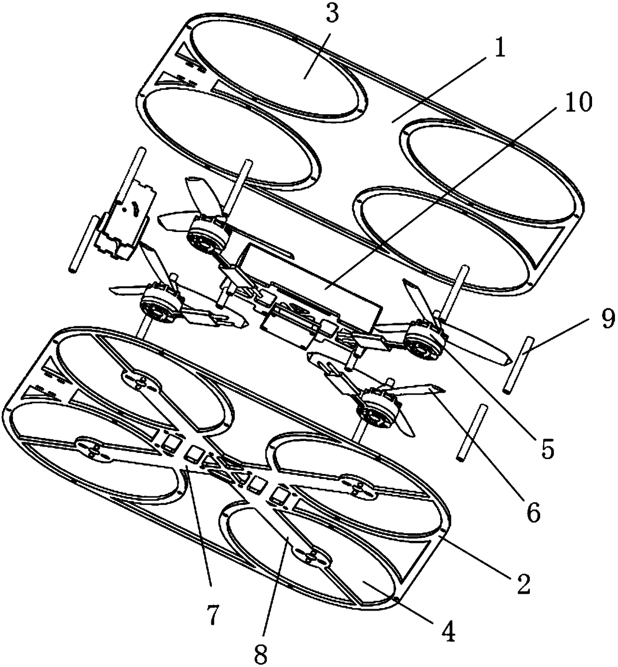
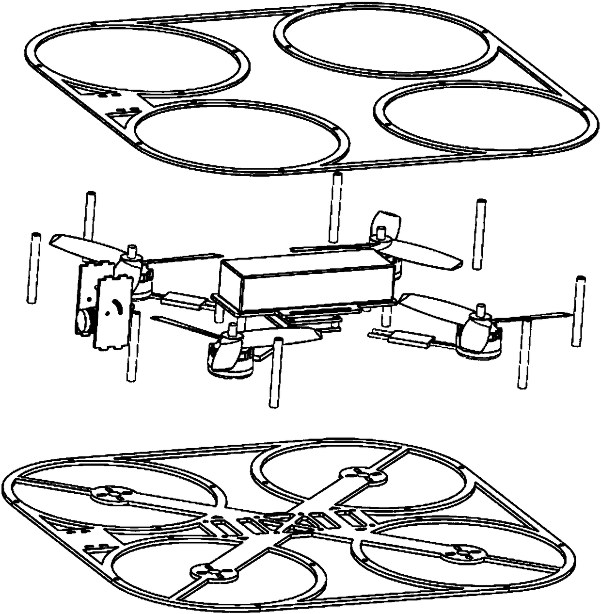
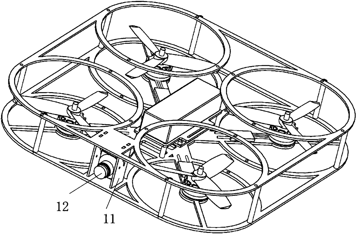
[0012] The specific implementation manner of the present invention will be described in detail below in conjunction with the accompanying drawings and preferred embodiments. Such as Figure 1-Figure 3 As shown, a UAV racing through training machine, including the upper rectangular arm 1, the lower rectangular arm 2, the upper perfect circular rotor arm 3, the lower perfect circular rotor arm 4, the motor 5 and the propeller 6 ;The upper rectangular arm 1, the lower rectangular arm 2, the upper circular rotor arm 3, and the lower circular rotor arm 4 are laminated and bonded by carbon fiber cloth through epoxy resin to form a carbon fiber plate, which is then cut by CNC An integrated high-strength carbon fiber frame is formed. The four inner corner positions of the upper rectangular guard arm are integrally connected with the upper perfect circular rotor guard arm; the inner four corner positions of the lower rectangular guard arm are integrally connected with the lower perfec...


PUM


Abstract

The invention relates to the technical field of unmanned aerial vehicles and particularly relates to a racing traversing exercise machine for an unmanned aerial vehicle. The exercise machine comprisesan upper rectangular protection arm, a lower rectangular protection arm, upper orbicular rotor wing protection arms, lower orbicular rotor wing protection arms, four motors and propellers, wherein the positions of four included angles at the inner side of the upper rectangular protection arm are integrally connected with the upper orbicular rotor wing protection arms respectively; the positions of four included angles at the inner side of the lower rectangular protection arm are integrally connected with the lower orbicular rotor wing protection arms respectively; a bottom plate is arranged at the center position of the lower rectangular protection arm, and two sides of the bottom plate are integrally connected with reinforcing plates respectively; the upper rectangular protection arm andthe lower rectangular protection arm are connected together through a connecting column; the four motors are respectively mounted on the reinforcing plates at the center position of the lower orbicular rotor wing protection arm; and the propellers are mounted at the output ends of the motors. By virtue of the unique design of the shape of an airframe, the stability and the reliability of a fuselage are enhanced, the service properties are reduced, and the flight safety is improved.

Description

technical field [0001] The invention relates to the technical field of unmanned aerial vehicles, in particular to an unmanned aerial vehicle racing through training machine. Background technique [0002] The full name of FPV is "First Person View". FPV usually refers to a drone controlled by a first-person perspective, also known as a traversing machine. Different from the aerial cameras known to the general public that pursue stability and shooting capabilities, FPV pursues speed, flexibility and flying experience. And the first-person perspective manipulation is performed through the image transmission system to achieve the perfect fusion of virtual and reality. The traditional traversal frame is composed of straight arms and carbon fiber four-axis multilateral center plate. The disadvantages are that the stability is not enough, the center of gravity is not well controlled, which is not conducive to the protection of the battery and flight control, and the battery will t...

Claims


Application Information

Patent Timeline
IPC IPC(8): B64C27/20
CPCB64C27/20B64U10/10
Inventor 赵昌丽侯硕刘颢张健苏宁波
Owner TIANJIN SINO GERMAN VOCATIONAL TECHNICAL COLLEGE
Features
  • Generate Ideas
  • Intellectual Property
  • Life Sciences
  • Materials
  • Tech Scout
  • Unparalleled Data Quality
  • Higher Quality Content
  • 60% Fewer Hallucinations
Learn More