Automatic plaiting method

A knitting and automatic technology, applied in braided fabrics, textiles and papermaking, etc., can solve problems such as difficult knotting, achieve the effect of solving difficult knotting, realizing continuous work, and improving production efficiency

Active Publication Date: 2018-07-06
YIBIN HIEST FIBER +1
View PDF8 Cites 10 Cited by
  • Summary
  • Abstract
  • Description
  • Claims
  • Application Information

AI Technical Summary

Problems solved by technology

[0012] The purpose of the present invention is to overcome the above-mentioned problems existing in the prior art, provide a kind of automatic knitting method, this invention provides the mode ...

Method used


Image

  • Automatic plaiting method
  • Automatic plaiting method
  • Automatic plaiting method

Examples


Embodiment 1

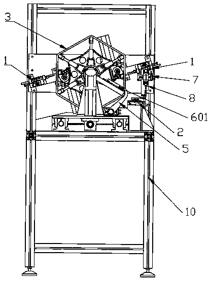
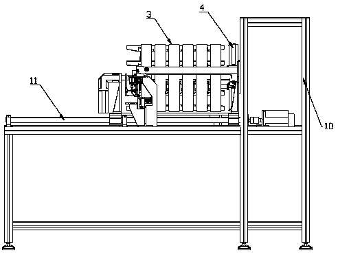
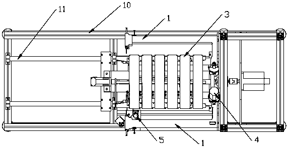
[0070] An automatic twisting method, comprising a winding mechanism 1 for winding the wires into bundles, an automatic knotter 2 for knotting the winding thread ends 14, the inner layer thread ends 12 and the outer layer thread ends 13, a wire frame 3 and a power system 4, The power system 4 drives the wire frame 3 to move axially and rotate around the axis under the winding mechanism 1; the winding mechanism 1 winds the wire harness in lanes; after winding, the winding thread 14, the inner thread 12 and the outer Layer thread end 13 is knotted through automatic knotter 2.

[0071] Further, the winding mechanism 1 of the present invention includes a needle bar 101 that reciprocates in the vertical direction, and the needle bar 101 is provided with a needle 102 with an upper thread for winding; The rotating hook 103 that rotates in a circle in the direction; the wire frame 3 is arranged between the needle bar 101 and the rotating hook 103 and presents a progressive movement.

...

Embodiment 2

[0100] The wire harness is placed on the wire frame 3, and the wire frame 3 is fixed on the present invention by the wire frame fixer. The needle bar 101 passes through the wire harness on the wire frame 3, moves to the lowest position and rises to form a wire loop I, and the wire loop I is immediately hooked by the rotating hook 103 that rotates counterclockwise 102; the needle bar 101 rises and exits the wire harness, and the rotating hook 103 pulls Lengthen and expand the thread loop I, the thread loop I slides to the middle, and the thread frame 3 advances; the needle bar 101 passes through the wire harness for the second time, and at this time the rotating hook 103 turns 180°; the needle bar 101 rises from the lowest position again and starts to form a thread Ring II, when the rotating hook 103 turns over 360°, hook into the wire ring II for the second time and stretch and expand the wire ring II, so that the wire ring II penetrates the wire ring I; the wire ring I slips o...


PUM


Abstract

The invention discloses an automatic plaiting method and belongs to the field of mechanical and electrical integration. The device provided by the invention comprises a winding mechanism, an automaticknotting device, a thread frame and a power system, wherein the winding mechanism is used for winding threads into bundles; the automatic knotting device is used for knotting wound thread heads, inner thread heads and outer thread heads. The method comprises the following steps: driving the thread frame to make an axial progressive movement under the action of the winding mechanism by the power system and enabling the thread frame to rotate around a shaft; winding wiring harnesses separately by the winding mechanism; knotting the wound thread heads, inner thread heads and outer thread heads by the automatic knotting device after winding completion. According to the method disclosed by the invention, an operation of completing separated winding by one thread by the winding mechanism is provided, a single-thread chain stitch manner is adopted for winding, the automatic winding function is completely realized, and one-shear thread opening of the formed strands can be realized in the subsequent procedure. The wound thread heads, the inner thread heads and the outer thread heads can be knotted by the automatic knotting device, a bionic hand knotting manner is realized, and the problemof knotting difficulty is effectively solved.

Description

technical field [0001] The invention relates to the technical field of electromechanical integration, in particular to an automatic knitting method. Background technique [0002] At present, after the silk threads in the textile industry at home and abroad are twisted, almost all of them adopt the method of manual twisting. The existing manual twisting actions include: [0003] 1. To send the bottom thread, the operator uses one hand to pull the silk thread drawn from the silk cake from the center of the skein frame waiting to be twisted, and pass from the bottom of the thread to the end; [0004] 2. To hook the bottom thread, the operator uses the finger of the other hand to insert the gap between the silk threads separated by the stranding machine on the twisting frame, and hook out the bottom thread, so that the bottom thread forms a circle on the finger above the silk thread ; [0005] 3. The operator rewinds the end of the bottom thread at the end and passes through t...

Claims


Application Information

Patent Timeline
IPC IPC(8): D04C3/00D04C3/48
CPCD04C3/00D04C3/48
Inventor 邓传东贺敏陈勇君雷生兰范贤珍陈绍武刘庭聪张建军
Owner YIBIN HIEST FIBER
Why Eureka
Try Eureka