Detachable iron tower coupling beam and transmission tower

A detachable, iron tower technology, applied in the field of transmission towers, can solve problems such as poor versatility and economy, inability to quickly put into use, and inability to achieve energy conservation and environmental protection.

Active Publication Date: 2018-07-06
GUANGZHOU POWER SUPPLY BUREAU GUANGDONG POWER GRID CO LTD
View PDF6 Cites 2 Cited by
  • Summary
  • Abstract
  • Description
  • Claims
  • Application Information

AI Technical Summary

Problems solved by technology

[0003] However, the connecting beams used for the support of the above-mentioned transmission towers are all reinforced concrete structures, and need to be poured integrally with the foundation columns of the tower. The construction is difficult and the steps are complicated, and it cannot be put into use quickly and cannot be recycled, so it cannot achieve energy saving and environmental protection; Each type of connecting beam can only be applied to the iron tower legs of one root opening size, which is poor in versatility and economy

Method used


Image

  • Detachable iron tower coupling beam and transmission tower
  • Detachable iron tower coupling beam and transmission tower
  • Detachable iron tower coupling beam and transmission tower

Examples


Embodiment Construction

[0030] In order to make the object, technical solution and advantages of the present invention clearer, the present invention will be further described in detail below in conjunction with the accompanying drawings and specific implementation methods. It should be understood that the specific embodiments described here are only used to explain the present invention, and do not limit the protection scope of the present invention.

[0031] It should be noted that when an element is referred to as being “fixed on”, “disposed on” or “installed on” another element, it may be directly on another element or there may be an intervening element. When an element is considered to be "connected" to another element, it may be directly connected to the other element or there may be an intervening element at the same time; the specific way in which an element is fixedly connected to another element may be achieved through existing technologies, and will not be discussed here. To repeat it aga...


PUM


Abstract

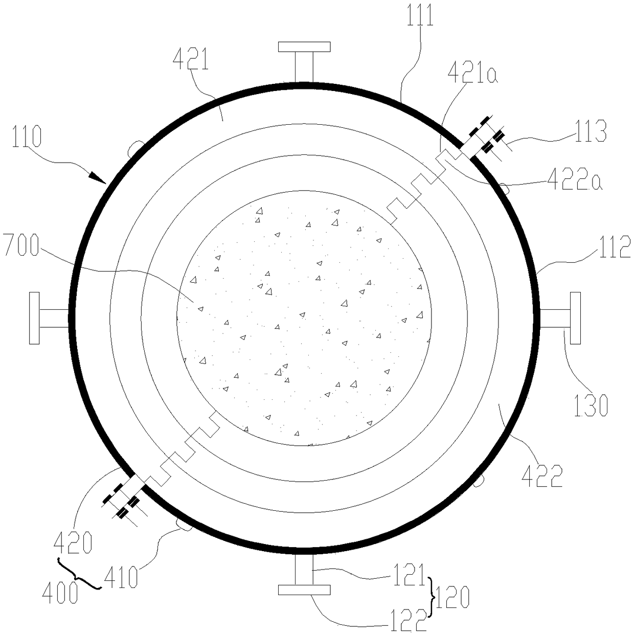
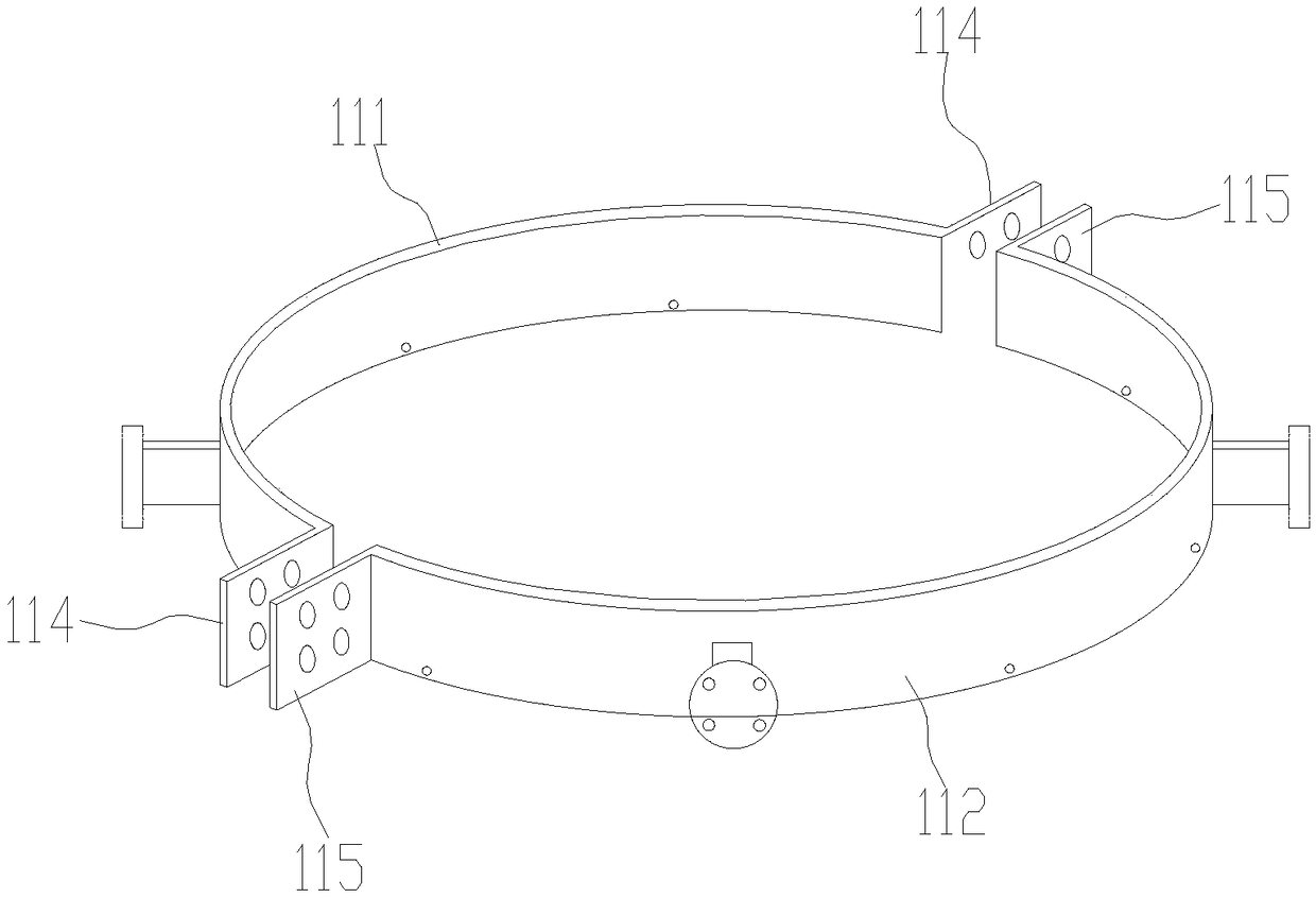
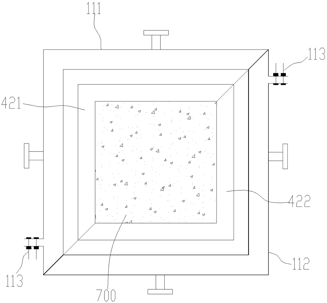
The invention discloses a detachable iron tower coupling beam and a transmission tower. The detachable iron tower coupling beam and the transmission tower comprises at least three tower legs embracinghoops, at least six first adjustable locking assemblies and at least three straight-side coupling beams, wherein the tower leg embracing hoops comprise an embracing hoop body connected with each of the tower legs in a fastening and fixing mode one by one, and at least two first fixed connecting seats arranged on the embracing hoop body at intervals; the first adjustable locking assemblies are connected with the first fixed connecting seats in a fastening and fixing mode one by one; and second fixed connecting seats are arranged on the two ends of each of the straight-side coupling beams, thesecond fixed connecting seats are connected with the first adjustable locking assemblies in a fastening and fixing mode one by one. The installation work of the coupling beam can be quickly achieved,the construction steps are simple and convenient, the use for support of damaged tower legs can be quickly put into, the disassembly can be achieved to facilitate the circulation use, and energy saving and environmental protection are achieved; and at the same time, by the trimming of the first adjustable locking assemblies, tower leg supports with different foot distance sizes in a certain rangecan be achieved, and universality and economy are good.

Description

technical field [0001] The invention relates to the technical field of power transmission towers, in particular to a detachable iron tower connecting beam and a power transmission tower. Background technique [0002] As the supporting carrier of the transmission cable, the transmission line iron tower plays a vital role in the safe operation of the power grid. The transmission line tower usually includes no less than three tower legs, and each tower leg adopts a different foundation. When designing the foundation of the tower, if the geology is not good or there is a weak layer on the ground surface, generally a reinforced concrete connecting beam will be designed to connect four The two foundation columns are connected into a whole to strengthen the integrity, rigidity and ability to resist horizontal lateral movement of the foundation. If the geology is good or in a mountainous area, in view of economic considerations, the coupling beam is generally not designed, but as t...

Claims


Application Information

Patent Timeline
Patent Type & Authority Applications(China)
IPC IPC(8): E04H12/08
CPCE04H12/08
Inventor 张记权江少镇张珏潘建庭万新董少波王学良黄小珈唐杰斌胡成乐徐敏于映坤李炯巴懿伯胡劭超张译文
Owner GUANGZHOU POWER SUPPLY BUREAU GUANGDONG POWER GRID CO LTD
Why Eureka
Try Eureka