Supercharge Your Innovation With Domain-Expert AI Agents!

Incoming flow pre-processing unit

A processing unit and airflow technology, applied in the direction of fluid flow, mechanical equipment, etc., can solve problems such as not being able to faithfully reflect the actual state around the aircraft, and achieve the effects of avoiding the formation of complex turbulence, low cost, and easy cleaning

Pending Publication Date: 2018-07-06
丰翼科技(深圳)有限公司
View PDF0 Cites 0 Cited by
  • Summary
  • Abstract
  • Description
  • Claims
  • Application Information

AI Technical Summary

Problems solved by technology

Existing airflow collection methods for aircraft such as aircraft models and UAVs are to directly collect the air around the aircraft or directly introduce the airflow through the pitot tube. Because the air around the aircraft will form various turbulence due to flight reasons, the ordinary airflow collection method cannot be true. Reflect the actual state around the aircraft

Method used


Image

  • Incoming flow pre-processing unit
  • Incoming flow pre-processing unit
  • Incoming flow pre-processing unit

Examples


Embodiment Construction

[0028] The following will clearly and completely describe the technical solutions in the embodiments of the present invention with reference to the accompanying drawings in the embodiments of the present invention. Obviously, the described embodiments are only some, not all, embodiments of the present invention. All other embodiments obtained by persons of ordinary skill in the art based on the embodiments of the present invention belong to the protection scope of the present invention.

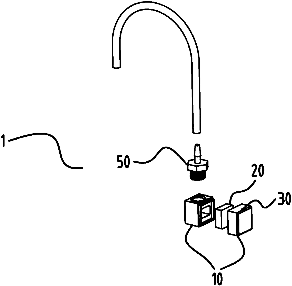
[0029] Such as figure 1 Shown is the incoming stream pre-processing unit 1 according to the embodiment of the present invention.

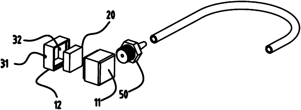
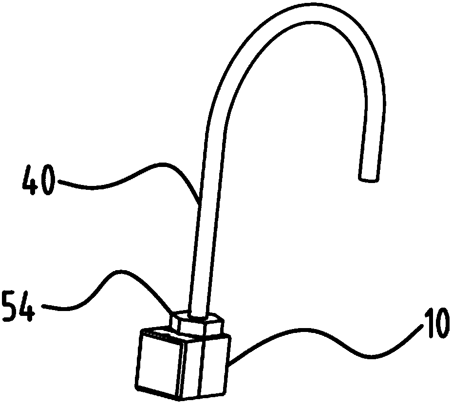
[0030] The incoming flow pre-processing unit 1 includes a housing 10, the housing 10 is provided with an introduction structure 30 for introducing airflow and an outlet structure for exporting airflow, an airflow channel is provided between the introduction structure 30 and the outlet structure, and a rectification structure is arranged in the airflow channel 20....


PUM


Abstract

The invention discloses an incoming flow pre-processing unit. The incoming flow pre-processing unit comprises a shell. The shell is provided with a guiding-in structure for guiding air flow in and a guiding-out structure for guiding the air flow out. An airflow channel is formed between the guiding-in structure and the guiding-out structure and internally provided with a rectifying structure. Therectifying structure is provided with a plurality of gaps capable of allowing the airflow to pass through. The incoming flow pre-processing unit has the beneficial effects that the incoming flow pre-processing unit is simple in structure and low in cost, after the airflow passes through the multiple gaps formed in the rectifying structure, local turbulence is eliminated, so that the phenomenon that measurement data are inaccurate due to local turbulence is avoided.

Description

technical field [0001] The invention relates to the technical field of airflow processing, in particular to an incoming flow pre-processing unit. Background technique [0002] In the field of flight or meteorology, it is often necessary to observe the atmosphere, and the observation of airflow is an important content of atmospheric observation. In the prior art, aircrafts such as model airplanes and unmanned aerial vehicles are usually used to observe high-altitude airflow or collect air pressure data. Existing airflow collection methods for aircraft such as aircraft models and UAVs are to directly collect the air around the aircraft or directly introduce the airflow through the pitot tube. Since the air around the aircraft will form various turbulence due to flight reasons, the ordinary airflow collection method cannot be true. Reflect the actual state around the aircraft. [0003] Aiming at the problems in the related technologies, no effective solution has been proposed...

Claims


Application Information

Patent Timeline
IPC IPC(8): F15D1/02
CPCF15D1/025
Inventor 雷鹏涛
Owner 丰翼科技(深圳)有限公司
Features
  • R&D
  • Intellectual Property
  • Life Sciences
  • Materials
  • Tech Scout
  • Unparalleled Data Quality
  • Higher Quality Content
  • 60% Fewer Hallucinations
Learn More