Method of delineating boundary of metal ore deposit affected by secondary fracture structure

A technology of fault structure and boundary, applied in the field of boundary delineation of metal ore deposits, can solve the problems of mine production difficulties, mine economic losses, ore body losses, etc., so as to avoid the increase of mining cost and construction difficulty, save ore body resources, reduce Effects of Ore Body Loss

Inactive Publication Date: 2018-07-06
武志明
View PDF3 Cites 6 Cited by
  • Summary
  • Abstract
  • Description
  • Claims
  • Application Information

AI Technical Summary

Problems solved by technology

[0003] In the actual prospecting process, due to the influence of cost, construction period, and construction conditions, it is impossible to control the mesh density too densely in drilling, and the structures and secondary structures that are not parallel to the main ore body are extremely developed. For the ore body delineated by the mining method, in the process of mining, it is often found that the boundary of the delineated ore body is very different from the actual boundary, which often leads to a large loss and dilution of the ore body
Also due to the occurrence of secondary faults between the sections, affected by their dislocation, after the local orebody dislocation shifts, the traditional method can no longer accurately delineate the orebodies only by using adjacent sections, which will easily lead to the failure of the upper and lower walls. Ore body loss or depletion, the phenomenon of ore body loss and depletion due to large changes in the ore body boundary has brought certain troubles to mining engineering, brought certain difficulties to mine production, and brought certain difficulties to the mine economic zone. It also wastes mineral resources and increases production costs. The above-mentioned shortcomings are extremely prominent in the Xinli mining area of ​​Sanshandao Gold Mine.

Method used


Image

  • Method of delineating boundary of metal ore deposit affected by secondary fracture structure
  • Method of delineating boundary of metal ore deposit affected by secondary fracture structure

Examples


Embodiment Construction

[0022] Embodiments of the technical solutions of the present invention will be described in detail below in conjunction with the accompanying drawings. The following examples are only used to illustrate the technical solutions of the present invention more clearly, and therefore are only examples, rather than limiting the protection scope of the present invention.

[0023] It should be noted that, unless otherwise specified, the technical terms or scientific terms used in this application shall have the usual meanings understood by those skilled in the art to which the present invention belongs.

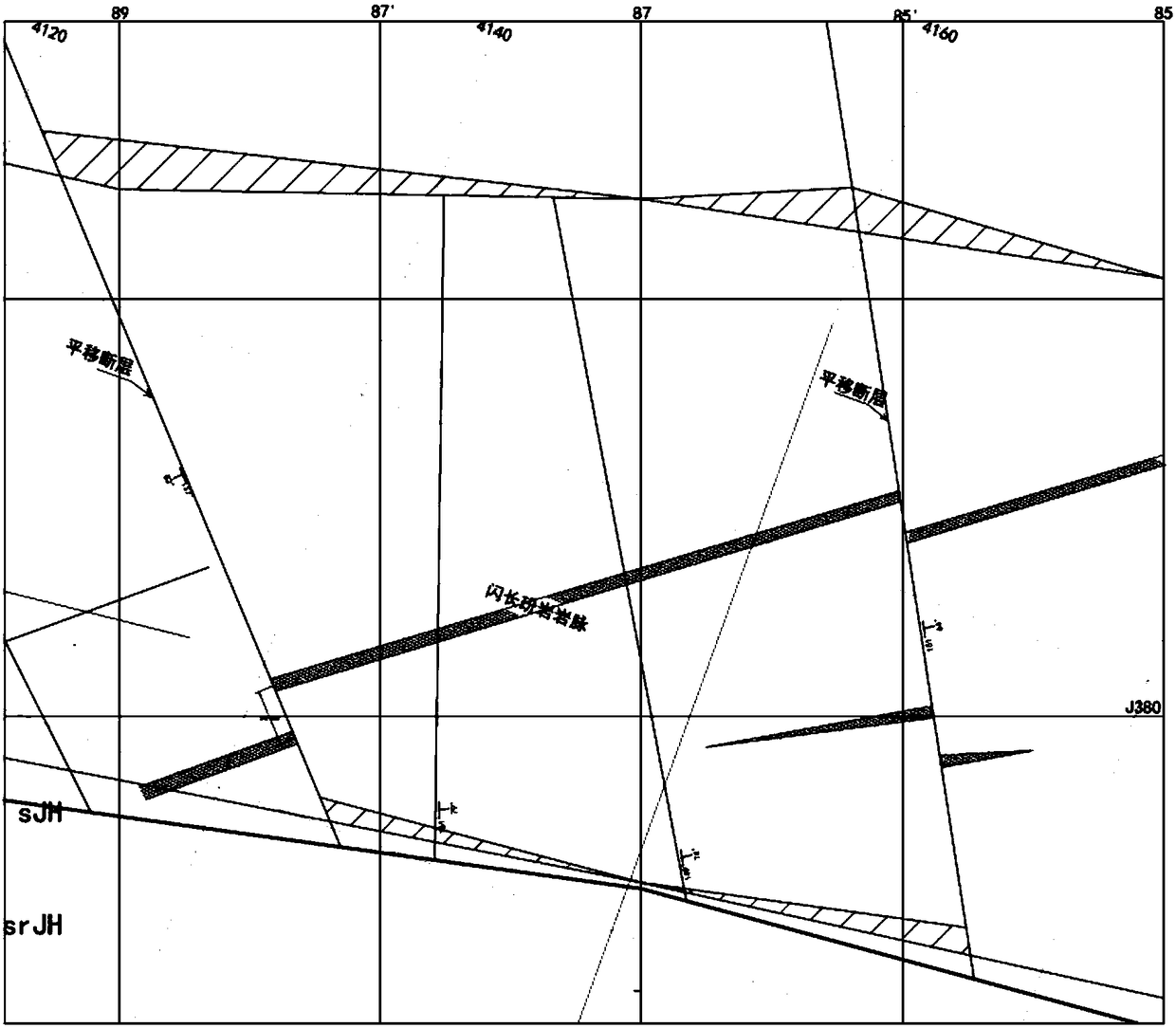
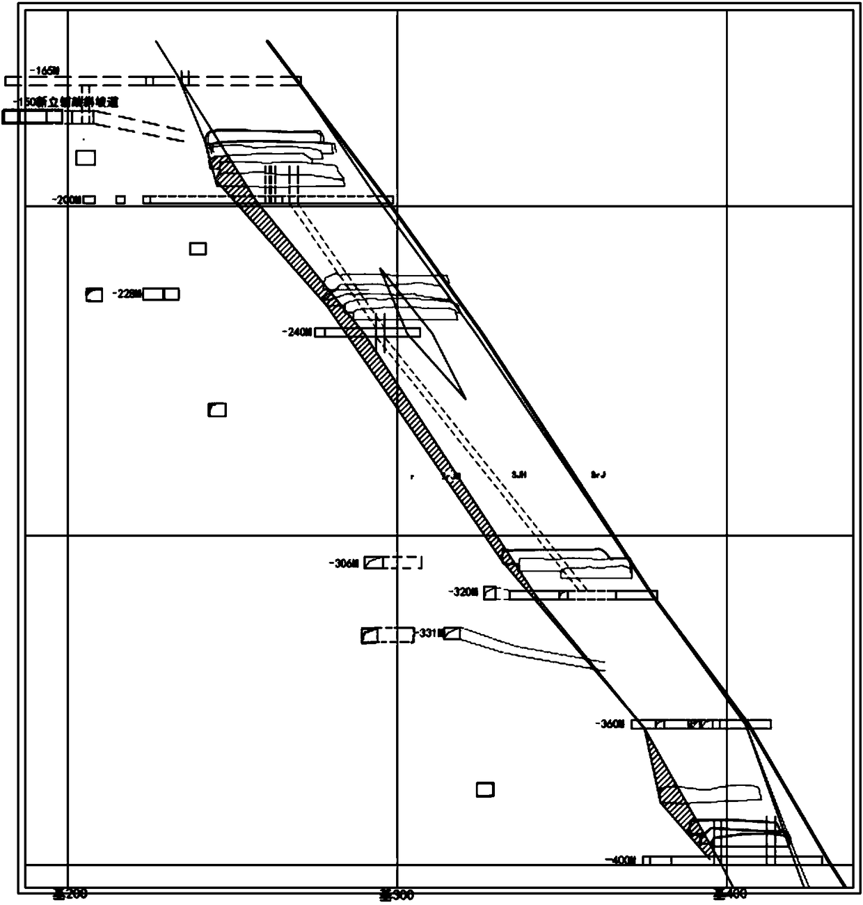
[0024] In order to clearly demonstrate the technical solution of the present invention, this application takes the Xinli mining area of ​​Sanshandao Gold Mine as an example for detailed description.

[0025] Geological overview: The Xinli gold deposit is located in the north-central part of the Sanshandao fault metallogenic belt, adjacent to the Sanshandao gold deposit in the north, ...


PUM


Abstract

The invention discloses a method of delineating the boundary of a metal ore deposit affected by the secondary fracture structure, comprising the following steps: S10, through the analysis of the existing regional geological data and the constructed reticular geological drilling / penetrating project, samples reaching the industrial boundary grade on adjacent sections are connected into an ore according to the sample test result obtained by the geological drilling / penetrating project, and the boundary of the ore body is preliminarily delineated; and S20, the surrounding rock and geological structure in the exposed tunnel / stratified stope are catalogued and mapped, and the boundary of the ore body is delineated for the second time based on the result in S10. According to the invention, the boundary of the ore body is determined through an ore delineating method combining mineral exploration engineering and structure. The precision of the boundary is improved. Accurate geological data is provided for mining and tunnel design. Ore body loss or dilution is reduced. Ore body resources are saved. The increase in mining cost and construction difficulty caused by the unclear boundary of the ore body is avoided.

Description

technical field [0001] The invention relates to the technical field of geological engineering exploration of metal mineral resources, in particular to a method for delineating the boundaries of metal deposits affected by secondary fault structures. Background technique [0002] The existing method of delineating the boundaries of metal mineral resources is mainly to carry out drilling or piercing engineering construction on the resource body according to a certain network degree, and then connect the samples that reach the industrial cut-off grade on the adjacent sections to form ore according to the test results of the samples. [0003] In the actual prospecting process, due to the influence of cost, construction period, and construction conditions, it is impossible to control the mesh density too densely in drilling, and the structures and secondary structures that are not parallel to the main ore body are extremely developed. During the mining process of the ore body deli...

Claims


Application Information

Patent Timeline
Patent Type & Authority Applications(China)
IPC IPC(8): G01V11/00
CPCG01V11/00
Inventor 武志明李龙胜蒋林峰段宝群
Owner 武志明
Why Eureka
Try Eureka