Feed structure for planar waveguide antenna

A planar waveguide and waveguide technology, which is applied in the connection of antenna grounding switch structures, waveguide devices, circuits, etc., can solve the problems of difficult size development, difficult to realize, and large space occupied by the overall line source, achieving low space occupancy and easy Conformal, flexible and convenient design effects

Pending Publication Date: 2018-07-06
SHEN ZHEN KUANG CHI HEZHONG TECH LTD
View PDF2 Cites 5 Cited by
  • Summary
  • Abstract
  • Description
  • Claims
  • Application Information

AI Technical Summary

Problems solved by technology

[0003] In practical application of CTS antenna, it is often difficult to provide an ideal feed line source with equal amplitude and same phase. The existing

Method used


Image

  • Feed structure for planar waveguide antenna
  • Feed structure for planar waveguide antenna
  • Feed structure for planar waveguide antenna

Examples


Embodiment Construction

[0033] Hereinafter, the present invention will be described in more detail with reference to the accompanying drawings. For the sake of clarity, various parts in the drawings have not been drawn to scale. Also, some well-known parts may not be shown. There are many specific details of the invention described below, but the invention may be practiced without these specific details, as will be understood by those skilled in the art.

[0034] It should be understood that when describing the structure of a component, when a layer or a region is referred to as being "on" or "over" another layer or another region, it may mean being directly on another layer or another region, or Other layers or regions are also included between it and another layer or another region. And, if the part is turned over, the layer, one region, will be "below" or "beneath" the other layer, another region.

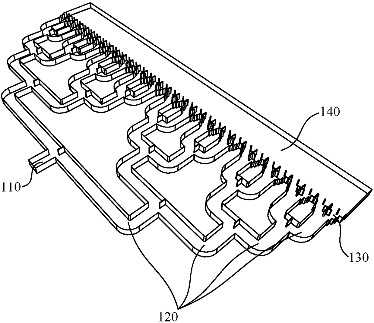
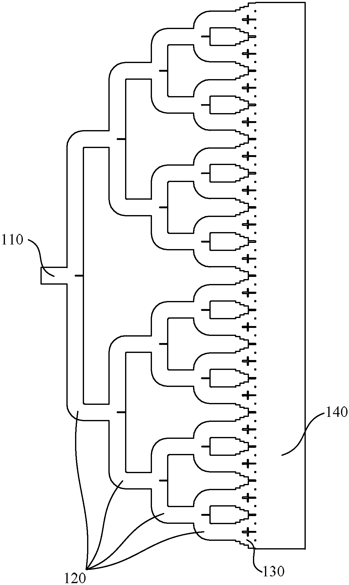
[0035] figure 1 with figure 2 The perspective view and the top view of the feed structure of ...


PUM


Abstract

The invention discloses a feed structure for a planar waveguide antenna. The feed structure comprises a rectangular waveguide, a multistage waveguide power division structure, a parallel-plate waveguide and a plurality of mode conversion structures, wherein the multistage waveguide power division structure is connected with the rectangular waveguide and is used for shunting an electromagnetic wavetransmitted in the rectangular waveguide; the plurality of mode conversion structures are used for connecting the multistage waveguide power division structure and the parallel-plate waveguide and are used for converting the mode of the electromagnetic wave and inputting the electromagnetic wave into the parallel-plate waveguide; and each mode conversion structure comprises a multistage stepped structure arranged on the side surface thereof, thereby reducing reflection of the electromagnetic wave. When the electromagnetic wave is transmitted into the parallel-plate waveguide from the rectangular waveguide and the multistage waveguide power division structure, conversion of the mode of the electromagnetic wave is completed through the mode conversion structures, the electromagnetic wave isconverted into a quasi transverse electromagnetic wave (TEM) mode from a TE mode, and quasi plane wave transmission is formed in the parallel-plate waveguide, so that the feed structure can be applied to a line source of a planar waveguide CTS antenna.

Description

technical field [0001] The present invention relates to the field of planar waveguide antennas, and more specifically, to a feeding structure of planar waveguide antennas. Background technique [0002] CTS (Continuous Transverse Stub, continuous transverse stub) antenna is a kind of planar waveguide antenna. This type of antenna realizes radiation by continuously opening and penetrating transverse slits on the planar waveguide and adding stubs to the transverse slits. At the same time, it uses TEM mode electromagnetic wave feed Electricity makes it have high feeding efficiency and aperture efficiency, and this kind of antenna is easy to process and low in cost, so it has a wide range of application prospects. [0003] In practical application of CTS antenna, it is often difficult to provide an ideal feed line source with equal amplitude and same phase. The existing method is to use the method of cylindrical parabola to design. The overall line source takes up a lot of space...

Claims


Application Information

Patent Timeline
IPC IPC(8): H01Q1/50H01P1/16
CPCH01P1/16H01Q1/50
Inventor 不公告发明人
Owner SHEN ZHEN KUANG CHI HEZHONG TECH LTD
Why Eureka
Try Eureka