
Thermal insulation constant-pressure compressed air energy storage system based on volatile fluid

A compressed air energy storage and volatility technology, applied in machines/engines, liquid variable capacity machinery, pump devices, etc. problems, to achieve the effect of improving energy utilization efficiency and reducing losses

Active Publication Date: 2018-07-10
QUANZHOU INST OF EQUIP MFG
View PDF7 Cites 6 Cited by
  • Summary
  • Abstract
  • Description
  • Claims
  • Application Information

AI Technical Summary

Problems solved by technology

[0004] Traditional CAES usually needs to store compressed air in underground caves, and harsh geographical conditions become the main factor limiting its promotion
At present, when the energy is released, the pressure of the compressed air decreases continuously with the reduction of the amount of compressed air. In order to ensure the stable operation of the expander, it is necessary to use the high-pressure air after throttling and reducing the pressure through the pressure stabilizing device, which wastes a lot of compression. energy, and the energy loss is caused by the throttling of compressed air
In addition, as the pressure in the air storage tank decreases, there will eventually be low-pressure air that is not utilized, compressed air is not fully utilized, and the utilization efficiency of the air storage tank is low

Method used


Image

  • Thermal insulation constant-pressure compressed air energy storage system based on volatile fluid
  • Thermal insulation constant-pressure compressed air energy storage system based on volatile fluid
  • Thermal insulation constant-pressure compressed air energy storage system based on volatile fluid

Examples


Embodiment Construction

[0030] In order to further explain the technical solution of the present invention, it will be described in detail below in conjunction with the accompanying drawings.

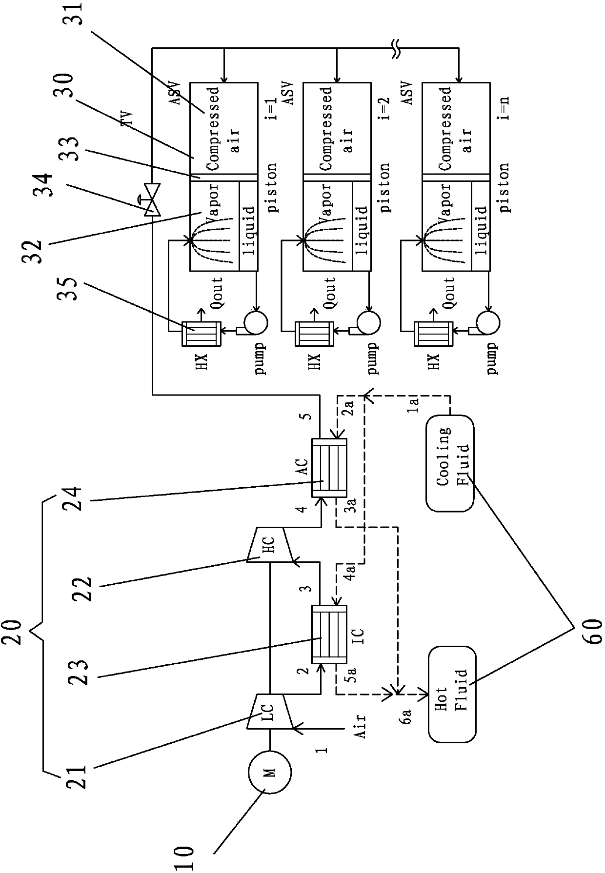
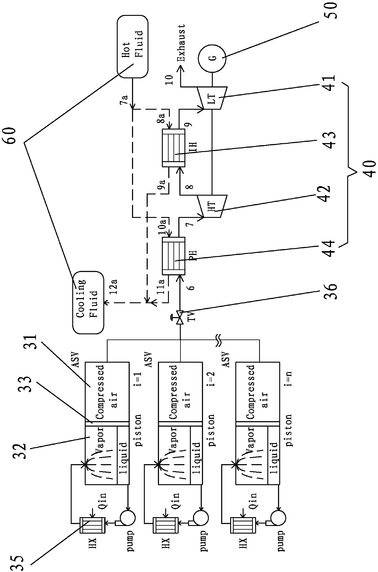
[0031] refer to Figure 1 to Figure 4 , the present invention includes a motor 10 , an air compressor unit 20 , an air storage tank 30 , an expansion unit 40 and a generator 50 .

[0032] The function of the air compressor unit 20 is to convert the excess electric energy of the grid into the pressure energy of compressed air. The air compressor unit 20 includes several air compressors. The compressors are connected in series through pipelines in order of design pressure from low to high, and can compress air to pressures corresponding to different power levels. The inlet pressure of the first air compressor is designed to be atmospheric pressure, and the inlet pressure of each subsequent air compressor is designed to be the outlet pressure of the previous air compressor. The outlet pressure of the last air c...


PUM


Abstract

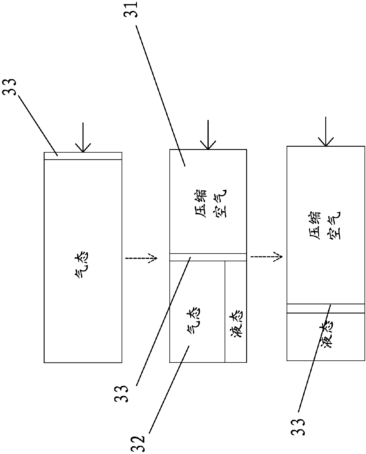
The invention discloses a thermal insulation constant-pressure compressed air energy storage system based on a volatile fluid. The system comprises a motor, an air compressor unit, an air storage tank, an expander unit and a generator; an output end of the motor is connected with an input end of the air compressor unit; an exhaust end of the air compressor unit is connected with an input end of the air storage tank; an output end of the air storage tank is connected with an intake end of the expander unit; and an output end of the expander unit is connected with the generator. The system further comprises a piston arranged in the air storage tank; an inner cavity of the air storage tank is divided into a first cavity and a second cavity by the piston; the piston is arranged in the air storage tank in a moving manner; the first cavity communicates with the exhaust end of the air compressor unit; and the volatile fluid is arranged in the second cavity. The system further comprises a heatexchange system for heat exchange with the second cavity. The system totally uses compressed air in the air storage tank, can reduce the exergy loss, and improves the energy utilization efficiency.

Description

technical field [0001] The invention relates to an adiabatic constant pressure compressed air energy storage system based on volatile fluid. Background technique [0002] With the continuous growth of energy demand, it is imperative to use energy efficiently, but the problems in the operation of the power grid have caused great waste and damage. Energy storage technology can improve the quality of electric energy and maintain the stability of the power system; overcome the intermittent characteristics of renewable energy (wind energy, solar energy, etc.), and use energy storage technology to "splicing" wind energy, solar energy and other energy sources to form a stable power supply direction. Users provide continuous power supply on demand; the energy storage unit forms a dispatchable unit, which stores and releases energy according to the valley and peak values ​​of the electricity price, improving the economic benefits of electricity. Adiabatic compressed air energy stora...

Claims


Application Information

Patent Timeline
Patent Type & Authority Applications(China)
IPC IPC(8): F01B23/10F04B37/12F04B41/02
CPCF01B23/10F04B37/12F04B41/02Y02E60/16
Inventor 汪凤翔陈龙祥谢媚娜
Owner QUANZHOU INST OF EQUIP MFG
Learn More