
Tool and method for measuring throw of steam turbine generating set hanger
A technology for turbogenerator sets and measuring tools, which is applied in the direction of angle/taper measurement, can solve the problems of large measurement errors and low operational safety, and achieve the effects of improving measurement accuracy, reducing operating procedures and measurement time
- Summary
- Abstract
- Description
- Claims
- Application Information
AI Technical Summary
Problems solved by technology
Method used
Image

Examples
Embodiment Construction
[0017] The tool and method for measuring the swing of the suspension shaft of a turbogenerator set according to the present invention will be described in detail below in conjunction with the accompanying drawings and embodiments.
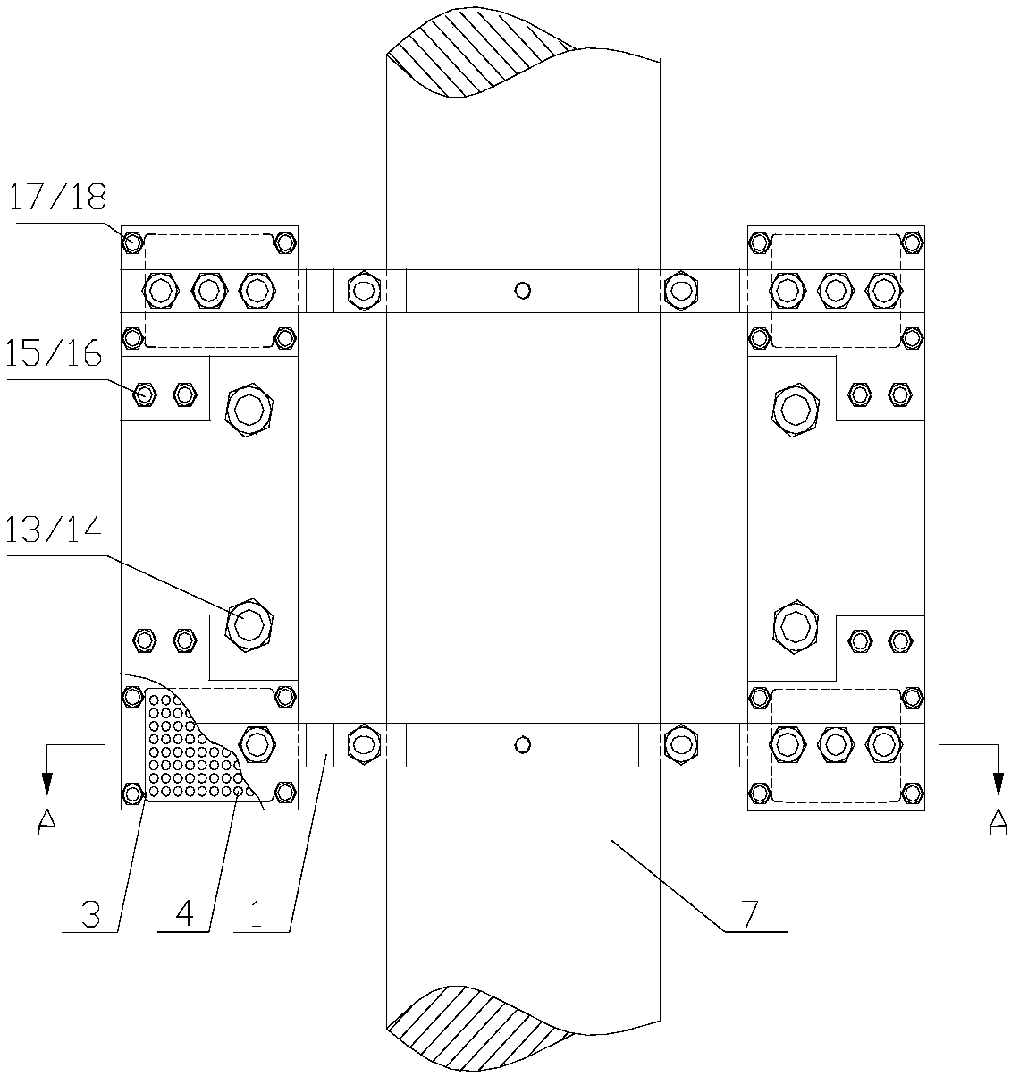
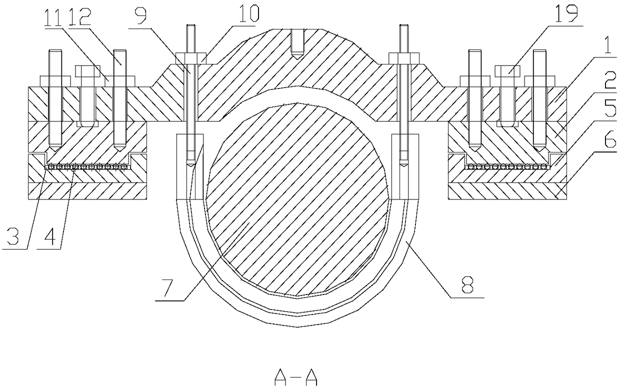
[0018] Such as figure 1 , figure 2 As shown, the suspension shaft swing measurement tool of the steam turbine generator set in this embodiment includes a support frame 1, a ball pressing plate 2, a ball support 3, a ball 4, a ball base 5, a swing frame base 6, an adjustment screw 9, an adjustment Nut 10 and floating hanging tile 8: pull the floating hanging tile 8 through the adjusting screw 9 to lift the rotor, and under the protection of the floating hanging tile 8, turn out the bearing bush of the bearing seat; Fall to the original position; at this time, the force of the rotor is distributed to the four ball pressing plates 2 through the two supporting frames 1 at the front and rear of the rotor. The ball pressing plates 2 are located on the ...
PUM
 Abstract
Description
Claims
Application Information