Gas sensing characteristic response curve testing device

A response curve and testing device technology, which is applied in the field of gas sensitive materials and gas sensors, can solve problems such as unsatisfactory, poor repeatability of test data, and low test accuracy of the response curve of gas sensitivity characteristics, so as to reduce the influence of gas sensitivity characteristics, Effects of Improving Test Accuracy and Confidence

Active Publication Date: 2018-07-10
合肥名龙电子科技有限公司
View PDF6 Cites 0 Cited by
  • Summary
  • Abstract
  • Description
  • Claims
  • Application Information

AI Technical Summary

Problems solved by technology

[0005] 1. Since the existing test device has an open structure and is in contact with external temperature, light and impurities, it is impossible to isolate the influence of external temperature, light and impurities on the gas-sensing characteristics, resulting in the test accuracy of the gas-sensing characteristic response curve not tall;
[0006] 2. The existing structure is an open structure, and the gas-sensitive material has adsorption on gas, which leads to the unstable state of the gas near the surface of the gas-sensitive material to be tested during the test, with large randomness and irregular changes, which leads to test results Low reliability and poor repeatability of test data, making gas sensitivity testing meaningless
[0007] 3. During the test, it may be necessary to load light of a specific wavelength under the premise of shielding the external temperature, light and impurities in order to study the influence of light on the response curve of the gas sensitivity characteristic. However, the existing technology cannot meet this technical requirement at all.

Method used


Image

  • Gas sensing characteristic response curve testing device
  • Gas sensing characteristic response curve testing device
  • Gas sensing characteristic response curve testing device

Examples


Embodiment Construction

[0020] Below in conjunction with accompanying drawing and embodiment the present invention will be further described:

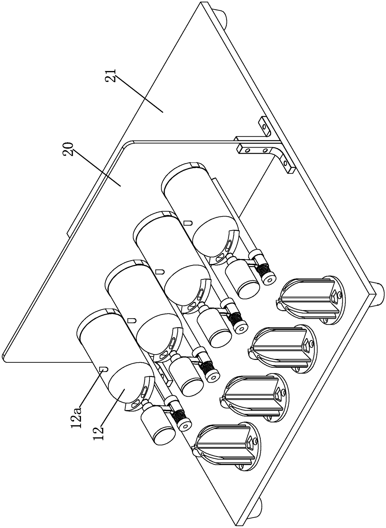
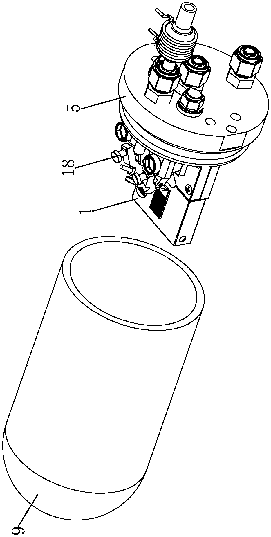
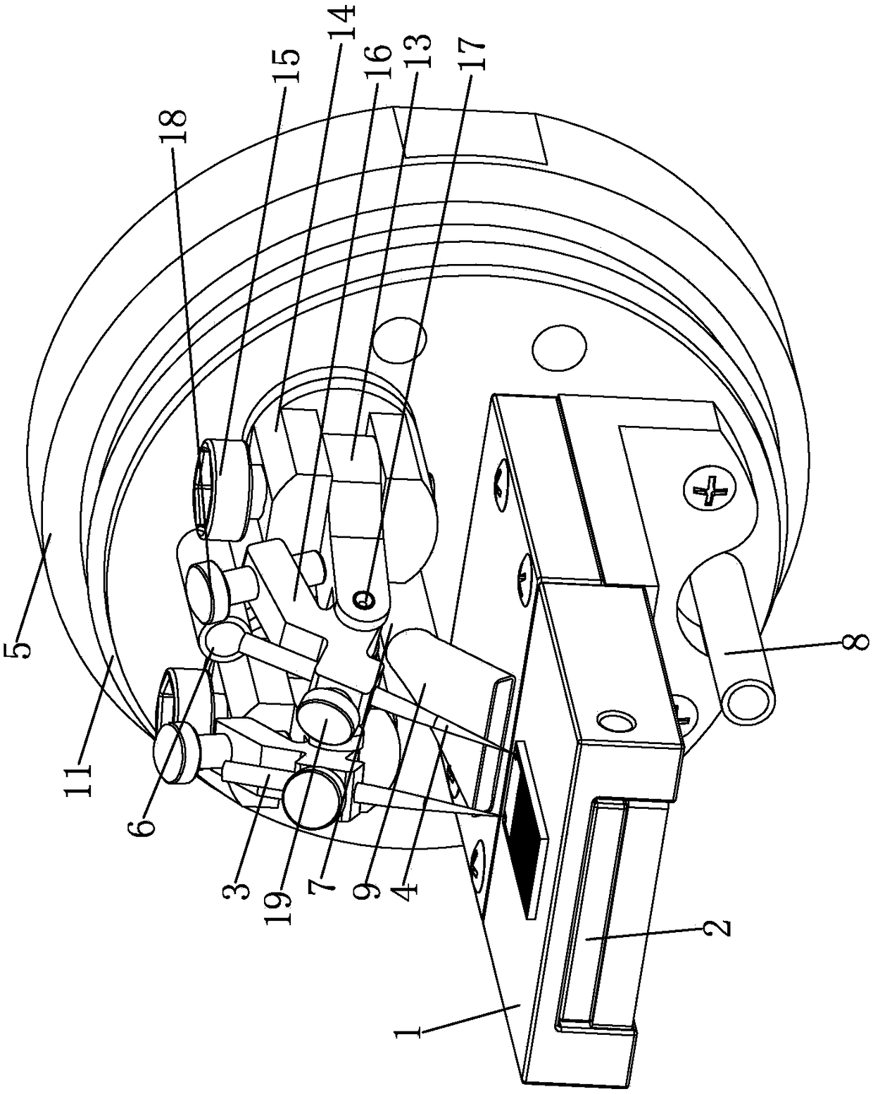
[0021] like figure 1 , 2 As shown in and 3, a gas sensitivity characteristic response curve testing device includes a sample carrier 1 and an inner cover 10, wherein the bottom of the sample carrier 1 is provided with a heating plate 2, and the top surface of the sample carrier 1 is used to carry the gas to be tested. gas-sensitive material, and the heating sheet 2 is a ceramic heating sheet. The first probe 3 and the second probe 4 are existing structures. During the test, these two probes are in contact with the surface of the gas-sensitive material to be tested. These two probes are respectively installed on the corresponding mounting components, and the sample load Both the platform 1 and the adjustment assembly are installed on the flange 5 . The first probe 3 and the second probe 4 are respectively connected to the measuring instrument through corres...


PUM


Abstract

The invention discloses a gas sensing characteristic response curve testing device. The bottom of a sample loading platform is provided with a heating piece. The top surface of the sample loading platform is used for bearing a gas sensing material to be detected. A flange disc is provided with a first gas inlet pipe, a second gas inlet pipe and a gas outlet pipe. The gas outlet end of the second gas inlet pipe is connected to a universal bamboo joint pipe. The first gas inlet pipe and the second gas inlet pipe are located above the sample loading platform. The universal bamboo joint pipe is close to the top surface of the sample loading platform. An inner cover is a transparent cover. The inner cover covers the sample loading platform, the heating piece, a first probe, a second probe, thefirst gas inlet pipe, the second gas inlet pipe, the gas outlet pipe and the universal bamboo joint pipe. The opening end of the inner cover is fixed to the excircle surface of the flange disc. The inner cover and the flange disc are sealed through O-shaped seal rings. Through use of the non-detachable transparent inner cover, heat isolation between the inner cavity of the inner cover and the environment is realized so that the heat isolation between the gas sensing material to be detected and the environment is realized and the influence produced by the environment temperature on the gas sensing properties is avoided.

Description

technical field [0001] The invention belongs to the field of gas-sensitive materials and gas-sensitive sensors, and in particular relates to a gas-sensitive characteristic response curve testing device, which can also be used in other fields related to gas pressure and components. Background technique [0002] As is well known to those skilled in the art, a gas sensor is made of a gas-sensitive material and is used to measure the type, concentration and composition of a gas, to detect a specific composition in the gas, and to convert the composition parameter into an electrical signal. Or device, it is also called gas sensor. The applications of gas sensors mainly include: carbon monoxide gas detection, gas gas detection, gas detection, Freon (R11, R12) detection, ethanol detection in exhaled breath, human oral bad breath detection, etc. [0003] The gas-sensing characteristic response curve of the gas-sensing material is an important parameter of the gas-sensing material, ...

Claims


Application Information

Patent Timeline
IPC IPC(8): G01N33/00G01N27/00
CPCG01N27/00G01N33/0009G01N33/0016
Inventor 龚恒翔
Owner 合肥名龙电子科技有限公司
Why Eureka
Try Eureka