Circuit breaker operating mechanism and assembling method thereof

A technology of operating mechanism and assembly method, applied in the direction of protection switch operation/release mechanism, contact drive mechanism, circuit, etc., can solve the problem that the stability of the moving contact is difficult to be guaranteed, the connection stability and elasticity are not enough, and the overall circuit breaker is affected Performance and other issues, to achieve the effect of facilitating automatic assembly, simplifying assembly difficulty, and improving reliability and stability

Active Publication Date: 2018-07-10
ZHEJIANG CHINT ELECTRIC CO LTD
View PDF6 Cites 7 Cited by
  • Summary
  • Abstract
  • Description
  • Claims
  • Application Information

AI Technical Summary

Problems solved by technology

However, with the trend of miniaturization design of circuit breakers, in order to simplify the structure, the part of the contact support is omitted, and when the support and limit of the contact support are lost, it is easy to appear that the moving contact moves along its axis of rotation. The phenomenon of shifting in the direction makes it difficult to guarantee the stability of the moving contact, thus affecting the overall performance of the circuit breaker
[0005] Moreover, in the existing circuit breaker operating mechanism, there is an elastic member between the lock catch used to cooperate with the electromagnetic tripping device and the circuit breaker housing, so as to ensure that the lock catch can move and reset. The elastic member usually adopts a torsion spring or an ordinary spring. Or it is not easy to install, or the connection stability and elasticity are not enough

Method used


Image

  • Circuit breaker operating mechanism and assembling method thereof
  • Circuit breaker operating mechanism and assembling method thereof
  • Circuit breaker operating mechanism and assembling method thereof

Examples


Embodiment Construction

[0036] The following is attached Figures 1 to 9 The given examples further illustrate the specific implementation of the circuit breaker operating mechanism and its assembly method of the present invention. The circuit breaker operating mechanism and its assembly method of the present invention are not limited to the description of the following embodiments.

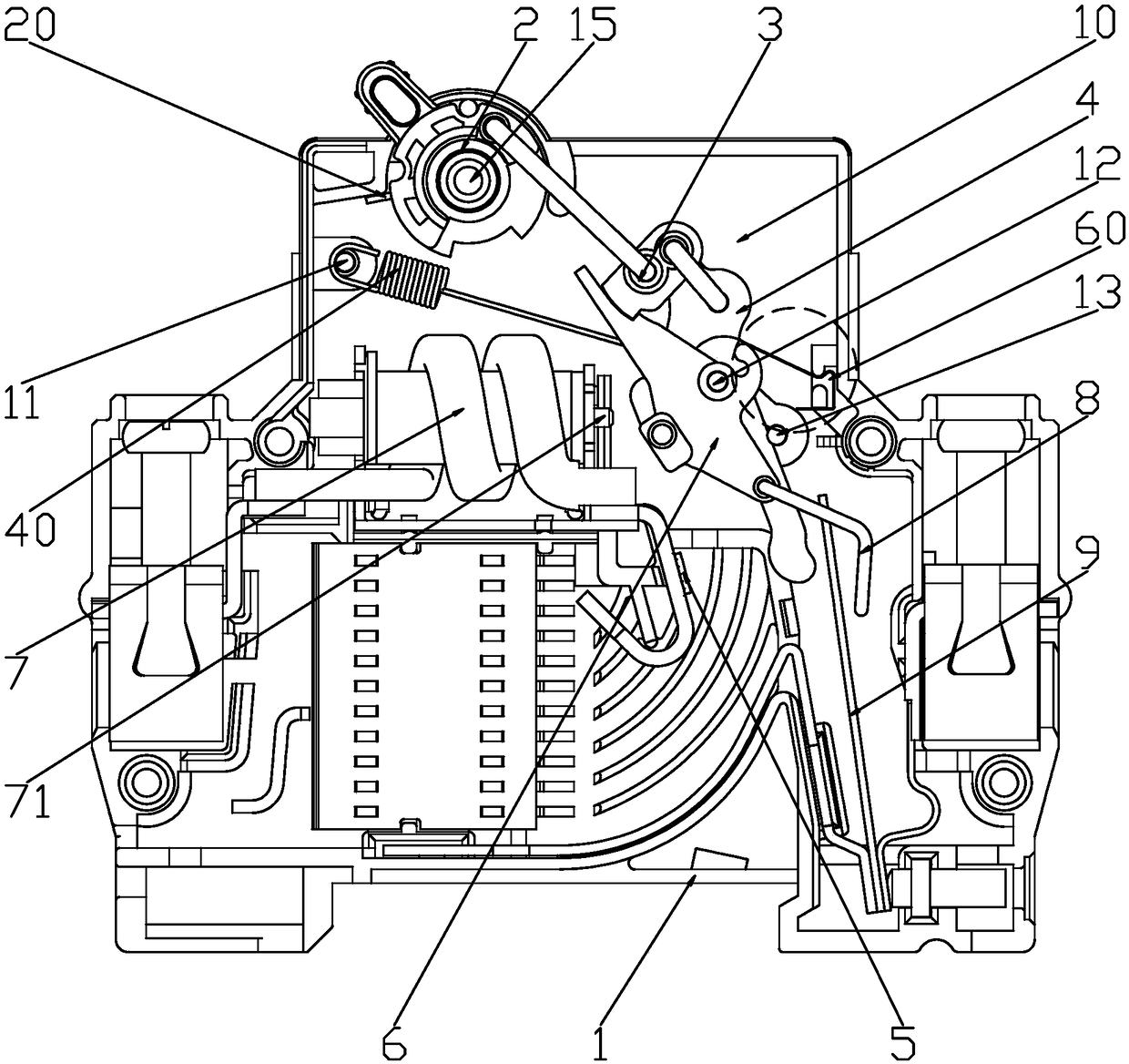
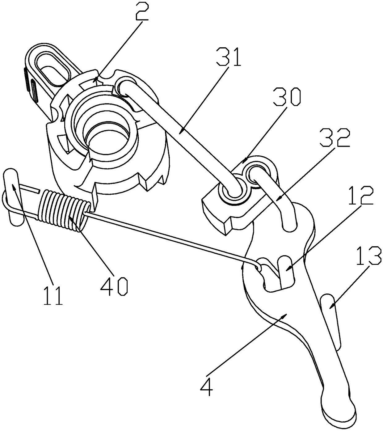
[0037] Such as figure 1 As shown, the operating mechanism of the circuit breaker of the present invention includes a handle 2, a movable contact 4 and a lock catch 6 which are respectively pivotally installed in the casing 1. The handle 2 is elastically connected between the first spring 20 and the casing 1. The connection realizes that the handle 2 can be reset, and the handle 2 is driven and connected with one end of the moving contact 4 through the transmission assembly 3, and the other end of the moving contact 4 is matched with the static contact 5 in the housing 1, and the moving contact The head 4 is elasticall...


PUM


Abstract

The invention discloses a circuit breaker operating mechanism and an assembling method thereof. The circuit breaker operating mechanism comprises a handle, a moving contact and a lock catch pivoted and mounted in a shell, wherein the handle is elastically connected with the shell through a first spring; the handle is in driving connection with the moving contact through a transmission assembly; the moving contact is elastically connected with the shell through a second spring; the connection rod of the transmission assembly is in buckle connection with the lock catch; and the lock catch is elastically connected with the shell through a third spring. The circuit breaker operating mechanism assembling method comprises steps: a handle rotation shaft, a mounting shaft and a supporting shaft are mounted on the bottom plate of the shell respectively; the first spring and the handle are sequentially mounted on the handle rotation shaft in a rotating mode; the moving contact is mounted on thesupporting shaft in a rotating mode; the transmission assembly is mounted on the handle and the moving contact in a stacked mode; two ends of the second spring are mounted on the mounting shaft and the moving contact; and the lock catch is mounted on the supporting shaft in a rotating mode. The circuit breaker operating mechanism and the assembling method thereof provided in the invention have theadvantages of simple structure and convenient assembly.

Description

technical field [0001] The invention relates to the field of low-voltage electrical appliances, in particular to a circuit breaker operating mechanism and an assembly method thereof. Background technique [0002] Circuit breakers utilize various means of unlatching mechanisms to detect faults and open circuits affected by the fault. The unlocking device includes a sensor and activates a mechanism of the circuit breaker which, upon detection of a fault, disengages the moving contacts from the stationary contacts. One type of trip device used in circuit breakers is the electromagnetic trip device, which is commonly used to open a circuit breaker during an emergency. An example of an electromagnetic trip device is a solenoid connected in series to the wires of the circuit breaker and arranged to activate the operating mechanism when the current in the wires exceeds a predetermined level. Another type of trip device used in circuit breakers is a thermal trip device, which is c...

Claims


Application Information

Patent Timeline
Patent Type & Authority Applications(China)
IPC IPC(8): H01H71/40H01H3/46H01H69/00
CPCH01H3/46H01H69/00H01H71/40
Inventor 唐皓朱俊司莺歌
Owner ZHEJIANG CHINT ELECTRIC CO LTD
Why Eureka
Try Eureka