Ignition device with flame stabilization function for liquid fuel ramjet engine

A ramjet and flame stabilization technology, applied in the field of ramjet, can solve the problems of increasing the complexity of the structure, low temperature of the oil and gas mixture, difficult gas ignition, etc., and achieve the effect of increasing the point or reliability, simplifying the assembly difficulty, and improving the reliability.

Inactive Publication Date: 2016-12-21
NANJING UNIV OF SCI & TECH
View PDF9 Cites 2 Cited by
  • Summary
  • Abstract
  • Description
  • Claims
  • Application Information

AI Technical Summary

Problems solved by technology

[0003] As far as the widely used spark plug igniter is concerned, its advantages are: simple equipment and high frequency; its disadvantages are: low ignition energy, only suitable for igniting gaseous fuel or atomized liquid fuel, low temperature of oil-gas mixture, The ignition area is small, and when there are pollutants between the electrodes, it is easy to cause ignition failure. When the gas flow rate is too high, it is difficult to ignite or it is easy to extinguish
[0004] Li Qing, Pan Yu, Tan Jianguo, etc. published in the "Comparative Analysis of the Performance of Flame Stabilizers with V-groove and V-grooves in Subcombustible Ramjet Engines [J]" (Journal of Aerodynamics, 2010, 25(01):35-40.) An ignition device with flame stabilization function for liquid ramjet engines is developed. Its working principle is to use spark plugs to ignite hydrogen-oxygen mixtures, and then use gas flames to ignite fuel-gas mixtures. The success rate of ignition has been improved, but it needs another Adding a hydrogen supply device greatly increases the complexity of the structure

Method used


Image

  • Ignition device with flame stabilization function for liquid fuel ramjet engine

Examples


Embodiment Construction

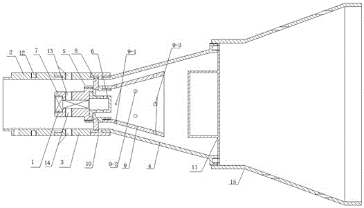
[0021] The present invention will be described in further detail below in conjunction with the accompanying drawings.

[0022] combine figure 1 , an ignition device for a liquid ramjet with a flame stabilization function, comprising an igniter, an oil supply passage 13, an air supply passage 14, a front casing 2, a middle casing 3, a connecting ring 10, a rear casing 4, an expansion Pipe 9, flame stabilizer 11, main combustion chamber flame stabilizer 15 and four fastening plugs 8, front housing 2 and middle housing 3 are fixedly connected by threads, middle housing 3 and rear housing 4 are connected by connecting ring 10 Fixed connection, the igniter is located at the junction of the middle housing 3 and the rear housing 4, the segmented design of the housing facilitates the installation of the igniter, four fastening plugs 8 are symmetrically distributed on the inner wall of the connecting ring 10, and the fastening plugs 8. One end is clamped between the connecting ring 10...


PUM


Abstract

The invention discloses an ignition device with flame stabilization function for a liquid fuel ramjet engine. A front shell is fixedly connected with a middle shell, the middle shell is fixedly connected with a rear shell through a connecting ring, an igniter is arranged at the joint of the middle shell and the rear shell, installation of the igniter is facilitated by sectional design of a shell, one end of a fastening plug is clamped between the connecting ring and the middle shell, the other end of the fastening plug is clamped on the igniter and functions in fixing the igniter, an oil supply channel passes the outer wall of the middle shell, extends into the shell and is fixedly connected with the igniter, a gas supply channel passes the outer wall of the middle shell, extends into the shell and is fixedly connected with the igniter, an expansion tube is fixedly connected with the igniter, a flame stabilizer is fixedly connected with the rear shell, and a main combustion chamber flame stabilizer is fixedly connected with the flame stabilizer. An not easily extinguished pioneer torch can be formed at the tail end of the igniter of the ramjet engine under high-speed airflow condition, the torch is used for igniting gas-oil mixture in a main combustion chamber, flame in the main combustion chamber can stably spread and cannot be easily extinguished, and the engine can normally work.

Description

technical field [0001] The invention belongs to the technical field of ramjet engines, and in particular relates to an ignition device for a liquid ramjet engine with a main combustion chamber flame stabilization function. Background technique [0002] A ramjet is an aeroengine with a simple structure, and its structure is generally composed of an air inlet, an ignition device, a combustion chamber, a flame stabilizer, and a nozzle. Due to the advantages of light weight and low cost, the ramjet engine is widely used as the power device for the cruising stage of the aircraft. Ignition device is an essential part set in the combustion chamber of liquid fuel ramjet engine for reliable ignition and stable combustion. [0003] As far as the widely used spark plug igniter is concerned, its advantages are: simple equipment and high frequency; its disadvantages are: low ignition energy, only suitable for igniting gaseous fuel or atomized liquid fuel, low temperature of oil-gas mixt...

Claims


Application Information

Patent Timeline
Patent Type & Authority Applications(China)
IPC IPC(8): F02C7/266F02K7/10
CPCF02C7/266F02K7/10
Inventor 袁一超封锋邓寒玉陈斌彬孔上峰
Owner NANJING UNIV OF SCI & TECH
Why Eureka
Try Eureka