High-energy ignition coil

a high-energy, ignition coil technology, applied in spark plugs, sparking gaps, machines/engines, etc., can solve the problem that the existing ignition coil cannot provide so much energy, and achieve the effect of improving energy conversion efficiency and increasing ignition energy

Inactive Publication Date: 2016-11-10
UNITED AUTOMOTIVE ELECTRONICS SYST
View PDF12 Cites 3 Cited by
  • Summary
  • Abstract
  • Description
  • Claims
  • Application Information

AI Technical Summary

Benefits of technology

[0009]The ignition coil of this application can regulate the on-time of the spark plug arbitrarily, and can thus increase the ignition energy to 400 mJ and more; besides, the ignition coil of this application uses a higher voltage to turn on the primary coil, thus improving the energy conversion efficiency.

Problems solved by technology

The existing ignition coil cannot provide so much energy.
A technical problem to be solved by this application is to provide a high-energy ignition coil that, instead of using a conventional energy-enhancing means, directly regulates the on-time of the spark plug (i.e., the time of duration when the gap between the two electrodes of the spark plug is broken down), thus enhancing the ignition energy of the ignition coil.

Method used


Image

  • High-energy ignition coil
  • High-energy ignition coil
  • High-energy ignition coil

Examples


Embodiment Construction

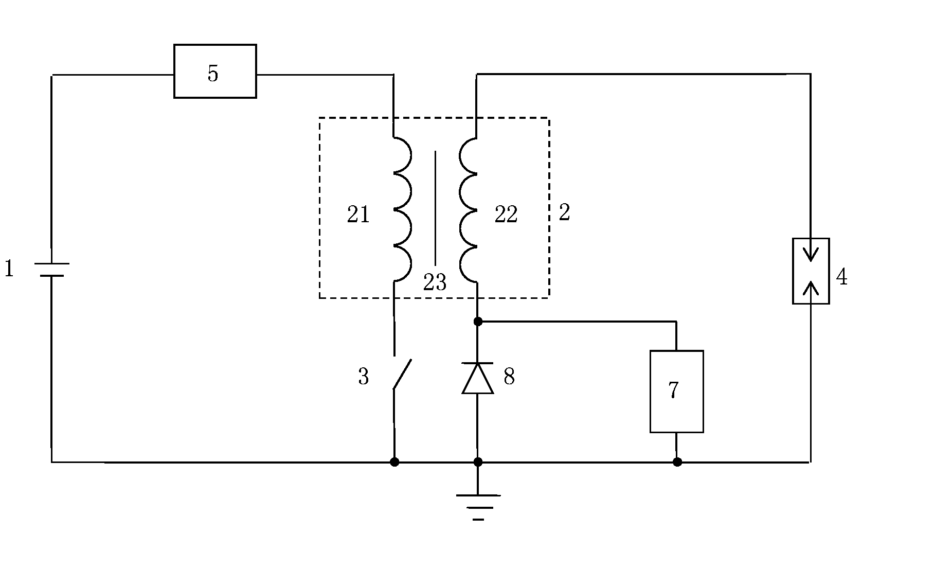
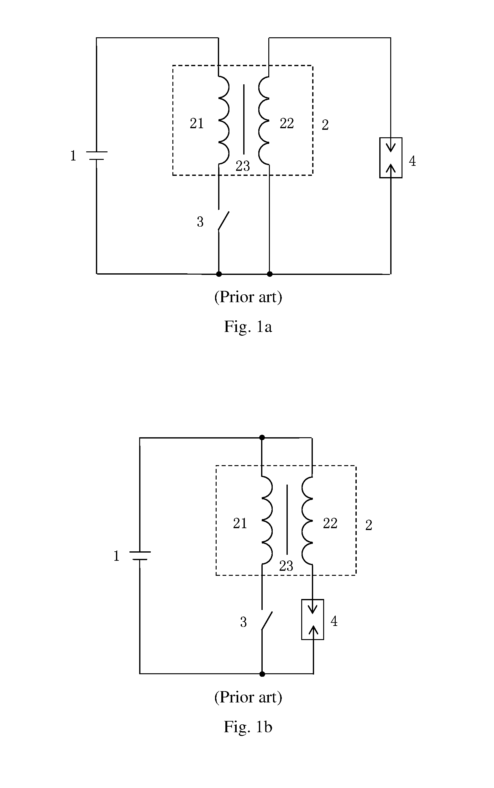
[0014]Referring to FIGS. 1a and 1b, the ignition energy value of the ignition coil is Q−∫0T(uISK-OUT×IOUT)dt. Wherein T is the discharge time of the secondary coil 22 in the secondary coil loop, UISK-OUT is the value of the voltage drop on the ground of an end of the secondary coil 22 that is connected to the spark plug 4, and iOUT is the value of the current flowing through the secondary coil (i.e., the secondary current).

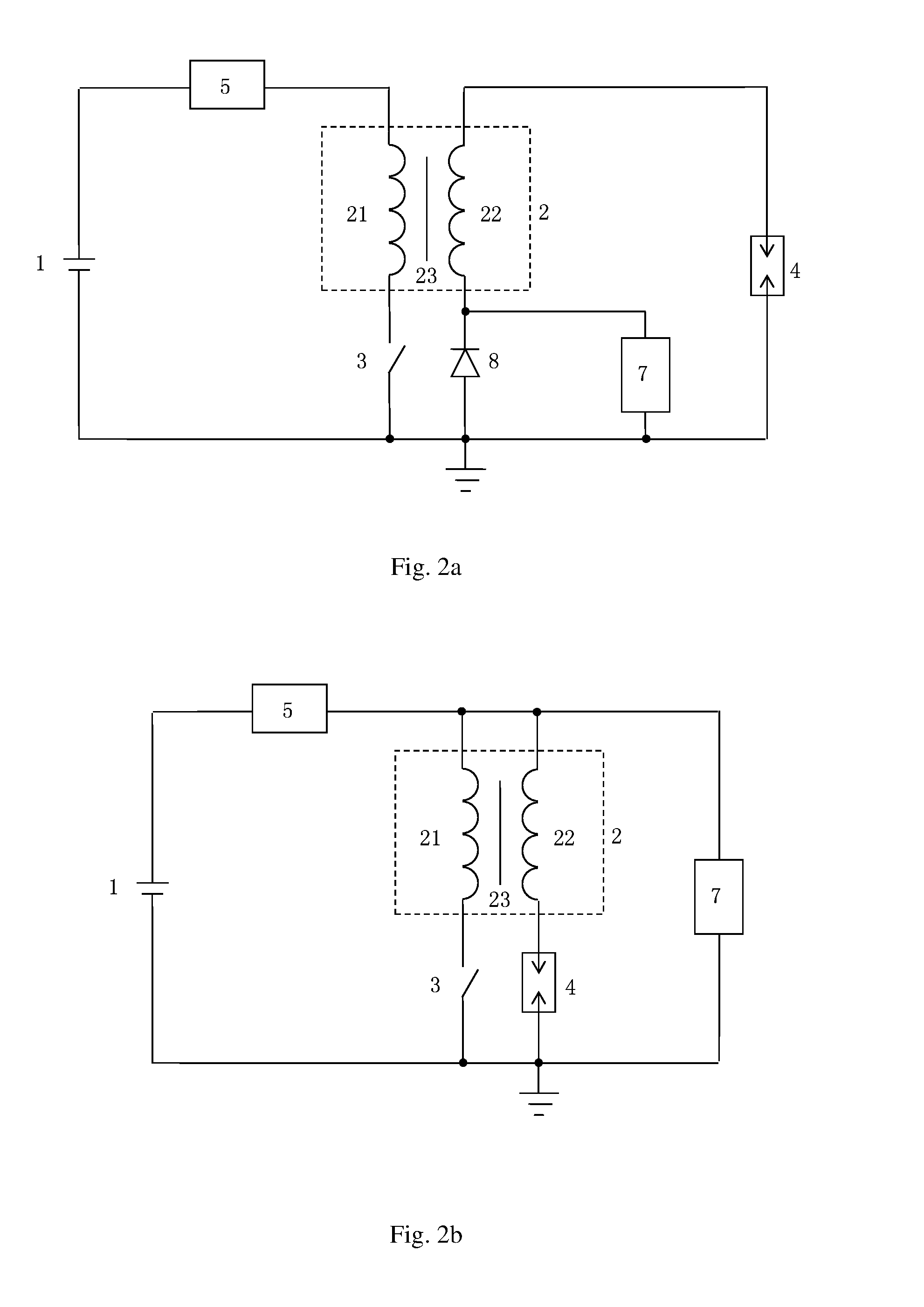
[0015]In the high-energy ignition coil of this application, discharge of the secondary coil 22 in the secondary coil loop can be divided into two stages: in the first stage, the energy of the primary coil 21 is coupled to the secondary coil 22 to make the spark plug 4 turned on; the first stage is from time 0 to time T1 for a duration of T1. In the second stage, the energy provided by the current keeping device 7 makes the spark plug 4 turned on; the second stage is from time T1 to time T1+T for a duration of T2. T=T1+T2. Therefore, the ignition energy value of th...


PUM

PropertyMeasurementUnit
rated voltageaaaaaaaaaa
discharge energyaaaaaaaaaa

Abstract

A high-energy ignition coil, wherein a primary coil and a secondary coil are both wound around an iron core, these three constituting a transformer. The primary coil loop is provided with a switch controlled by an ECU. The spark plug is connected at one electrode to an end of the secondary coil, and is grounded at the other electrode. An on-board power supply supplies power to the primary coil via a DC booster, which boosts the DC voltage outputted by the on-board power supply before outputting. The other end of the secondary coil is either connected to the DC booster or grounded via a reversely connected diode. A current keeping device is connected in parallel with a serial branch of the secondary coil and the spark plug, working after the spark plug is turned on to keep the spark plug on.

Description

FIELD OF THE INVENTION[0001]This application relates to an ignition coil used in a vehicle with an internal combustion engine.BACKGROUND OF THE INVENTION[0002]FIG. 1a shows an existing ignition coil. An on-board power supply 1, used for supplying power to a primary coil 21, is usually a low-voltage DC power supply at a rated voltage of 8-16 V. The on-board power supply 1 and the primary coil 2 constitute a primary coil loop, in which is provided a switch 3 controlled by an ECU (Electronic Control Unit). A secondary coil 22 is grounded at one end, and is connected at the other end to one electrode of a spark plug 4, with the other electrode of the spark plug 4 grounded. The secondary coil 22 and the spark plug 4 constitute a secondary coil loop. The primary coil 21 and the secondary coil 22 are both wound around an iron core 23, these three constituting a transformer 2.[0003]The ignition coil shown in FIG. 1a may be also modified as shown in FIG. 1b, wherein the secondary coil 22 is ...

Claims


Application Information

Patent Timeline
Patent Type & Authority Applications(United States)
IPC IPC(8): F02P3/08H01T15/00H01F38/12
CPCF02P3/0807F02P3/0876H01T15/00H01F38/12F02P3/0407F02P3/05F02P9/002F02P9/007F02P15/10F02P3/00H01T13/00
Inventor MAO, YICHUNSUN, XIAOQINGLI, YUQIANGCHENG, JIE
Owner UNITED AUTOMOTIVE ELECTRONICS SYST
Why Eureka
Try Eureka