Capacitive Ignition System

a capacitive ignition and capacitive technology, applied in the direction of ignition safety means, machines/engines, mechanical devices, etc., can solve the problems of prolonging the life of the ignition device (preferably configured as a spark plug), shortening the specific discharge time, and increasing the ignition energy requirement.

Active Publication Date: 2013-08-15
MAN ENERGY SOLUTIONS SA
View PDF17 Cites 4 Cited by
  • Summary
  • Abstract
  • Description
  • Claims
  • Application Information

AI Technical Summary

Benefits of technology

[0011]This causes the life of the ignition device (which is preferably configured as a spark plug) to be prolonged, particularly when using high ignition energy. Consequently, wear of the ignition device is reduced through the reduction in breakdown voltage by making selective use of the surge characteristic.
[0018]According to yet another embodiment of the invention, the second control device is constructed to increase the electrical capacitance as the ignition energy requirement of the ignition device increases so as to counteract a shortening of the specific discharge time caused by the increase in the ignition energy requirement.
[0019]According to an embodiment of the invention, the second control device is constructed to increase the electrical resistance as the ignition energy requirement of the ignition device increases so as to counteract a shortening of the specific discharge time caused by the increase in the ignition energy requirement.
[0020]According to another embodiment of the invention, the second control device is constructed to increase the electrical inductance as the ignition energy requirement of the ignition device increases so as to counteract a shortening of the discharge time caused by the increase in the ignition energy requirement.

Problems solved by technology

This causes the life of the ignition device (which is preferably configured as a spark plug) to be prolonged, particularly when using high ignition energy.

Method used


Image

  • Capacitive Ignition System
  • Capacitive Ignition System

Examples


Embodiment Construction

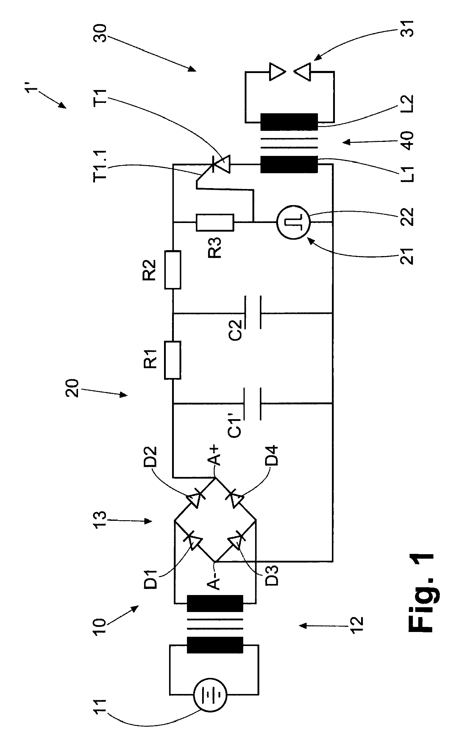
[0031]FIG. 1 shows a schematic diagram of a prior art capacitive ignition system 1′ of an internal combustion engine (not shown in its entirety).

[0032]The ignition system 1′ has a primary voltage source 10, a primary circuit 20, a secondary circuit 30 and a voltage converter 40 which is connected between the primary circuit 20 and the secondary circuit 30.

[0033]The primary voltage source 10 has an electric battery 11 providing DC current, a step-up converter 12 and a rectifier 13. The rectifier 13 has four diodes D1-D4 which are connected to one another to form a full-wave bridge rectifier 13. The step-up converter 12 is constructed in such a way that it increases the voltage supplied by the battery 11 to a primary voltage of approximately 300 to 400 volts. Two voltage source terminals A+, A− of the primary voltage source 10 are formed at the rectifier 13.

[0034]The primary circuit 20 has an electrical capacitance in the form of two capacitors C1′ and C2 (a first capacitor C1′ and a ...


PUM


Abstract

A capacitive ignition system for an internal combustion engine includes a voltage converter which has two primary terminals and two secondary terminals a primary voltage source has two voltage source terminals (A+, A−) which are connected in each instance to one of the primary terminals so that a primary circuit is formed; a switch which is incorporated within the primary circuit and a controller so that the switch can be closed and opened; a first control device constructed to actuate the controller in accordance with an ignition pattern for closing and / or opening; an electrical capacitance (C1, C2) within the primary circuit; and a second control device (25) constructed to maintain constant a voltage rise at the secondary terminals, which occurs in order to reach the ignition voltage, as the ignition energy requirement of an ignition device connected to the secondary terminals changes.

Description

BACKGROUND OF THE INVENTION[0001]1. Field of the Invention[0002]The invention is directed to a capacitive ignition system for an internal combustion engine.[0003]2. Description of the Related Art[0004]A capacitive ignition system is known, e.g., from U.S. Pat. No. 5,245,965A.[0005]It is currently common in capacitive ignition systems, starting from a minimum required ignition energy with new spark plugs (as ignition device), to provide an effective ignition energy which increases over an aging process of the spark plugs by raising the primary voltage.[0006]By raising the primary voltage such that only the available energy is increased, the voltage that can be tapped by the spark plug at the secondary terminals of the voltage converter rises more steeply prior to breakdown and arcing. This effect escalates spark plug damage and, as a result, shortens the life of the spark plug.[0007]It is an object of the present invention to provide a capacitive ignition system which allows the life...

Claims


Application Information

Patent Timeline
Patent Type & Authority Applications(United States)
IPC IPC(8): F02P1/08
CPCF02P1/08F02P3/0876F02P3/0846F02P11/02F02P3/08F02P3/06F02P7/06F02P7/0634F02P9/002
Inventor DIRUMDAM, BJORNSOLER, EDWIN CRUZ
Owner MAN ENERGY SOLUTIONS SA
Why Eureka
Try Eureka