Plasma ejection igniter

A plasma and igniter technology, used in weapon accessories, fuzes, offensive equipment, etc., can solve the problems of long ignition time, slow reaction speed, easy to detonate, etc., and achieve high ignition energy, long action time, and small size. Effect

Active Publication Date: 2010-03-17
HENGYANG TRANSISTOR
View PDF4 Cites 3 Cited by
  • Summary
  • Abstract
  • Description
  • Claims
  • Application Information

AI Technical Summary

Problems solved by technology

The chemical reagent layer is manually applied, which is difficult to guarantee the quality, and the reaction speed is slow, th

Method used


Image

  • Plasma ejection igniter
  • Plasma ejection igniter
  • Plasma ejection igniter

Examples


Example Embodiment

[0009] The present invention will now be described in detail with reference to the embodiments shown in the drawings.

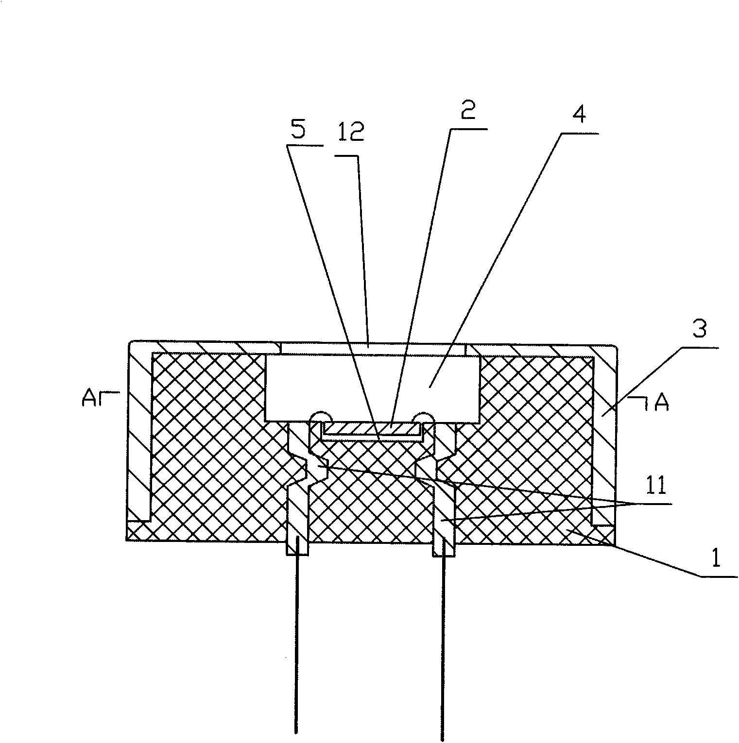
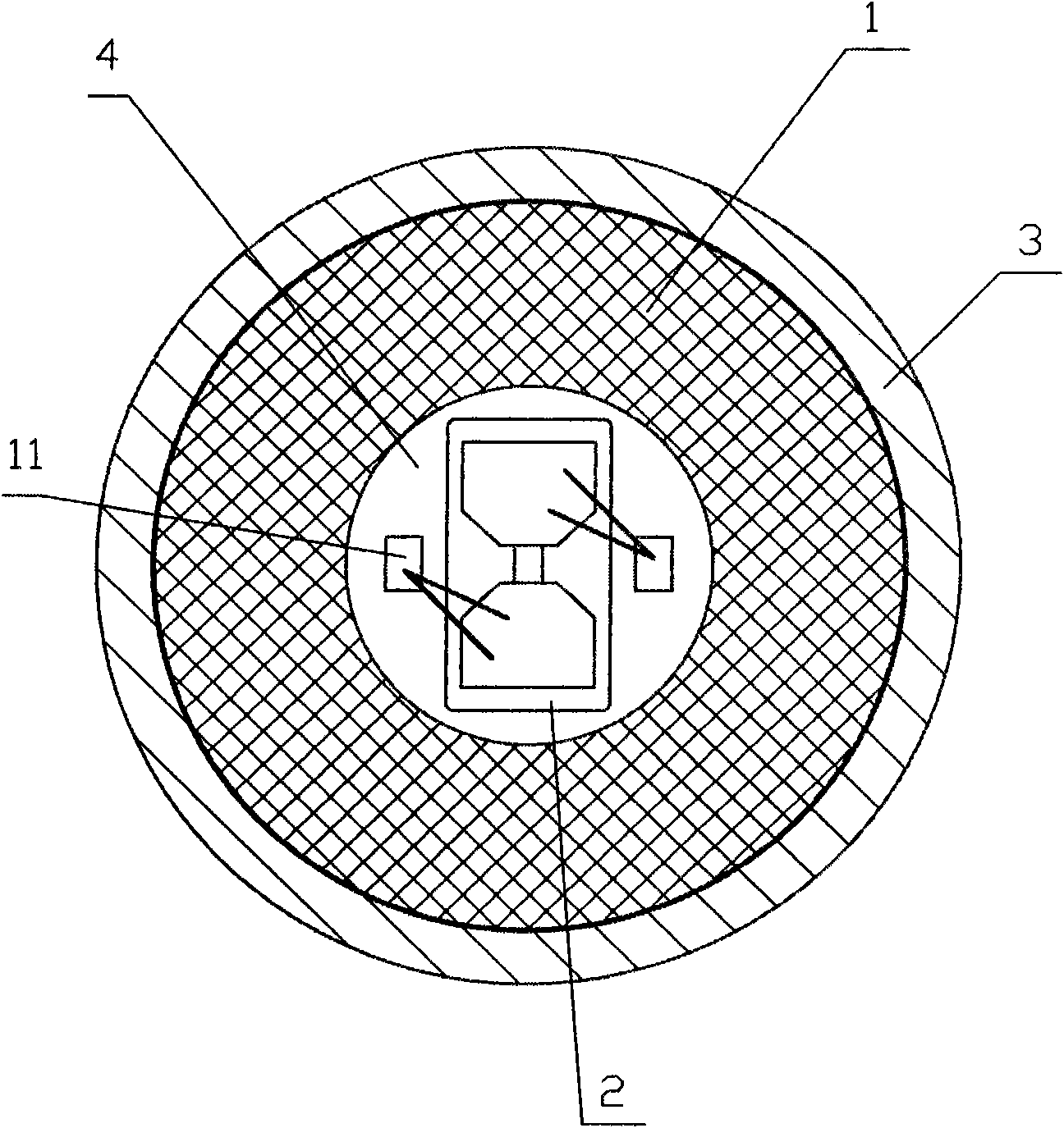
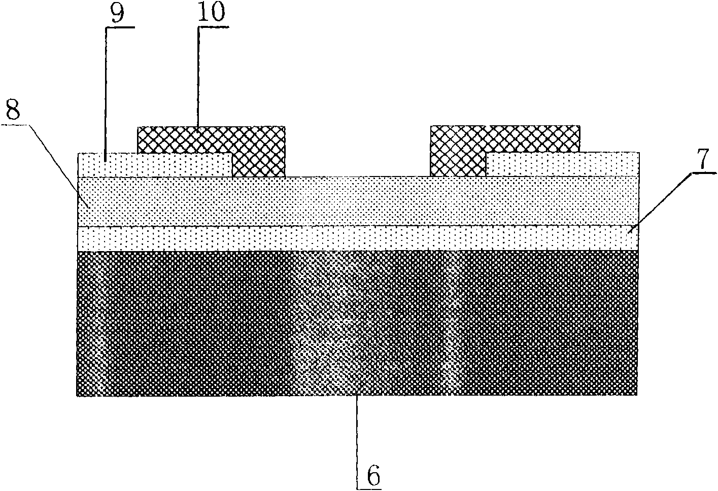
[0010] As shown in the figure, the plasma jet igniter is composed of an inverted cylindrical double-pit injection molding base 1, a polysilicon plasma ignition chip 2, and an outer shield 3. The top surface of the base 1 is sequentially recessed into a circular upper recess Pit 4, square bottom pit 5, polysilicon plasma ignition chip 2 from bottom to top are monocrystalline silicon substrate 6, insulating dielectric bottom layer 7, polysilicon mass 8 with thin film layer outside, insulating dielectric layer 9, metal thin film electrode The bonding pad 10, the chip 2 is adhered in the lower pit 5 in the base 1, the squished electrode lead 11 is drawn out through the cavity in the lower part of the base 1, and the chip 2 and the electrode lead 11 are packaged in the base 1 , The top surface of the outer shield 3 corresponding to the pit of the base 1 is provided w...


PUM


Abstract

The invention relates to a plasma ejection igniter, which is characterized by comprising a base provided with an upper concave pit and a lower concave pit which are formed by a top surface denting downwards, a polysilicon plasma ignition chip and an external protective cover; the chip and an electrode conductive piece thereof are encapsulated in the base; the upper top surface of the external protective cover is provided with an fire ejection port corresponding to the upper concave pit of the base; and the external protective cover is blocked outside the base. The traditional hot bridge wire ignition technology is replaced by a giant-heat and high-speed ejection polysilicon plasma particle ignition technology, and the mass blocks of the polysilicon is instantly melted from solid to liquidand then gasified into gas to form high-temperature and high-pressure impactive polysilicon plasma through the constraint of the two concave pits; the polysilicon plasma is constrained by the upper concave pit and enters a linear accelerating chamber to finish accelerated ejection. The igniter has low ignition energy, short ignition action time, is suitable for automatic large-scale production, can be used in high-temperature and high-pressure environments, and is safe and reliable.

Description

technical field [0001] The invention relates to an ignition device, in particular to a plasma jet igniter. Background technique [0002] At present, in the ignition device of a civil electric detonator, the ignition element is to coat a layer of chemical reagent on the thermal bridge wire, and heat the bridge wire through a large current in the bridge wire, so that the chemical reagent coated on the bridge wire Heating to ignite. The chemical reagent layer is manually applied, which is difficult to guarantee the quality, and the reaction speed is slow, the ignition time is long, and it is easy to detonate in a high temperature and high pressure environment, and the safety is poor. Contents of the invention [0003] The object of the present invention is to overcome the above disadvantages in the prior art, and provide a plasma jet igniter with small volume, short action time, safety, reliability and strong environmental adaptability. [0004] In order to achieve the purp...

Claims


Application Information

Patent Timeline
IPC IPC(8): F42C19/12
Inventor 费凡李爱夫
Owner HENGYANG TRANSISTOR
Why Eureka
Try Eureka