
Open-loop driving circuit for optimizing silicon carbide MOSFET turn-on waveform

An open-loop drive, silicon carbide technology, applied in circuits, electrical components, electronic switches, etc., can solve the problems of detection circuit susceptible to interference, gate voltage overshoot, large gate voltage, etc., to break the reverse current spike Contradictions with turn-on losses, suppressing gate voltage overshoot, and accelerating transient processes

Pending Publication Date: 2018-07-10
TSINGHUA UNIV
View PDF0 Cites 6 Cited by
  • Summary
  • Abstract
  • Description
  • Claims
  • Application Information

AI Technical Summary

Problems solved by technology

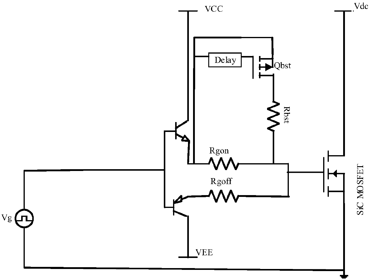
[0008] 2) The gate voltage overshoot is serious, and the gate voltage overshoot usually exists in the t3-t4 stage, and the gate damping resistance in this stage is R gon The equivalent resistance connected in parallel with Rbst, the damping is smaller, and the gate voltage spike will be larger
Closed-loop drive has disadvantages such as complex circuit, high cost, and detection circuit is susceptible to interference.
Although the open-loop drive circuit has the advantages of simple circuit and easy implementation, it is difficult for the current open-loop drive to suppress the reverse current peak and gate voltage overshoot while optimizing the turn-on loss.

Method used


Image

  • Open-loop driving circuit for optimizing silicon carbide MOSFET turn-on waveform
  • Open-loop driving circuit for optimizing silicon carbide MOSFET turn-on waveform
  • Open-loop driving circuit for optimizing silicon carbide MOSFET turn-on waveform

Examples


Embodiment Construction

[0035]Embodiments of the present invention are described in detail below, examples of which are shown in the drawings, wherein the same or similar reference numerals designate the same or similar elements or elements having the same or similar functions throughout. The embodiments described below by referring to the figures are exemplary and are intended to explain the present invention and should not be construed as limiting the present invention.

[0036] Before introducing the open-loop drive circuit that optimizes the turn-on waveform of the SiC MOSFET, first introduce the traditional SiC MOSFET drive circuit.

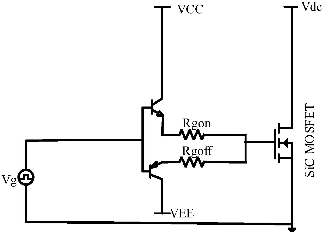
[0037] Silicon carbide MOSFET has the characteristics of high blocking voltage, high junction temperature and high switching speed, and is expected to replace Si IGBT. Such as figure 2 As shown, the traditional driving circuit of SiC MOSFET can only control the gate resistance R gon Controls the turn-on waveform. Under the bridge arm structure, using the tradit...


PUM


Abstract

The invention discloses an open-loop driving circuit for optimizing silicon carbide MOSFET turn-on waveform. The circuit comprises a driving voltage waveform generator for producing driving voltage waveform of a preset rising edge; a gate pole changing driving resistance control circuit for controlling the size of the gate pole driving resistance at different stages of the turn-on transient process, wherein the grid source voltage change rate of the silicon carbide is in consistent with the driving voltage rising change rate at the current rising stage, thereby controlling the current rising change rate and reverse current by controlling the driving voltage rising change rate; the gate pole current is increase at the voltage falling stage, thereby accelerating the voltage falling process and reducing the turn-on loss; the gate pole damping resistance is increased at the breakover-stabilizing stage, thereby suppressing the gate pole voltage overshooting without influencing the on-off speed. The driving circuit is simple in structure, easy to realize, low in cost, and capable of suppressing the reverse current peak and the gate pole voltage overshooting under the condition of reducing the turn-on loss.

Description

technical field [0001] The invention relates to the technical field of power electronic circuits, in particular to an open-loop drive circuit for optimizing the turn-on waveform of a silicon carbide MOSFET. Background technique [0002] Silicon carbide MOSFET is a new type of power semiconductor, and there is still a certain distance from large-scale industrialization. Due to the fast switching speed of silicon carbide devices, the gate voltage will have more serious gate oscillation and overshoot, which may break down the gate oxide layer and cause permanent failure of the device. The larger current change rate will bring more serious electromagnetic interference and Large turn-on reverse current. Although CREE and other manufacturers provide drivers, the driver can only change the switching transient process of SiC MOSFET by changing the gate resistance, and can only balance the compromise of gate voltage overshoot and switching loss, switching speed and switching loss, a...

Claims


Application Information

Patent Timeline
IPC IPC(8): H03K17/687H03K17/0814
CPCH03K17/08142H03K17/6877H03K2217/0036
Inventor 陆海峰韩洋柴建云李永东
Owner TSINGHUA UNIV
Learn More