Winged insect catching device

A technology for capturing devices and flying insects, which is applied to devices for catching or killing insects, applications, animal husbandry, etc. It can solve the problems of low reliability, single working mode, and high limitations in use, and achieve improved reliability, The effect of various working modes and low limitation of use

Inactive Publication Date: 2018-07-13
林翰
View PDF6 Cites 1 Cited by
  • Summary
  • Abstract
  • Description
  • Claims
  • Application Information

AI Technical Summary

Problems solved by technology

[0002] As we all know, the flying insect catching device is a device for catching harmful flying insects in agricultural planting to prevent them from infringing on agriculturally planted crops. The existing flying insect catching device includes connecting rods, two sets of slide rails, fixed frame, fixed plate, handle and sticky insect net, the top of the connecting rod is connected with the bottom end of the fixed frame, the inside of the fixed frame is provided with a placement cavity, the top of the fixed frame is provided with a pick-and-place opening, and the take-out The opening is communicated with the placement cavity, and the front side wall and the rear side wall of the fixing frame are respectively provided with two groups of through holes, and the two groups of through holes are all communicated with the placement cavity, and the sticky insect net card is mounted on the fixed plate, and fixed The plate is fixed between the two sets of slide rails, and the bottom end of the connecting rod is connected to the top of the handle; when this flying insect trapping device is in use, the user holds the handle and drives the handle to move, so as to drive the connecting rod and simultaneously Drive the fixed plate to move, so as to drive the sticky insect net to capture flying insects near the working environment; It has high limitations and low practicability; moreover, it requires the user to manually control the work, and the work efficiency is low, resulting in low reliability in use

Method used


Image

  • Winged insect catching device
  • Winged insect catching device
  • Winged insect catching device

Examples


Embodiment Construction

[0014] The specific embodiments of the present invention will be described in further detail below in conjunction with the drawings and embodiments. The following examples are used to illustrate the present invention, but not to limit the scope of the present invention.

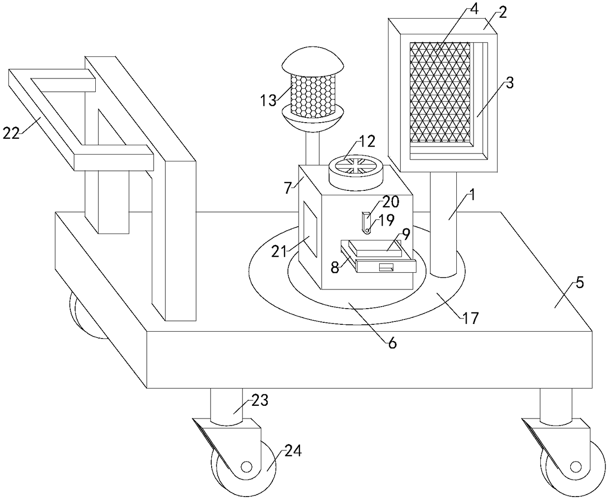
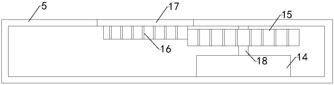
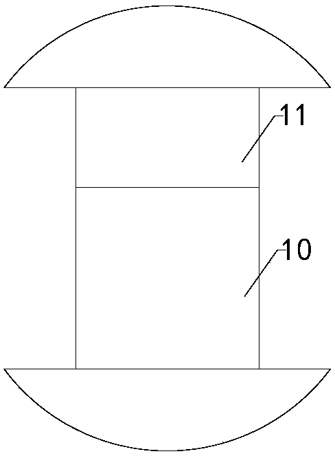
[0015] Such as Figure 1 to Figure 3 As shown, a flying insect catching device of the present invention includes a connecting rod 1, two sets of slide rails, a fixing frame 2, a fixing plate 3, and a sticky insect net 4. The top end of the connecting rod is connected to the bottom end of the fixing frame, and the fixing frame A placing cavity is provided inside, the top of the fixing frame is provided with a taking and placing opening, which communicates with the placing cavity. The front and rear side walls of the fixing frame are respectively provided with two sets of through holes, and the two sets of through holes are connected with the placing The cavities are connected, the sticky insect network card is i...


PUM


Abstract

The invention relates to the technical field of environmentally-friendly agriculture, in particular to a winged insect catching device. According to the winged insect catching device, the working modes are various, a winged insect can be effectively attracted, the limitation of use is lower, and the practicability is higher; the device can be automatically controlled, and the work efficiency is higher, thereby improving the use reliability; the winged insect catching device comprises a connecting rod, two sets of slide rails, a fixing frame, a fixing plate and an insect sticking net, wherein the top end of the connecting rod is connected with the bottom end of the fixing frame, the insect sticking net is clamped on the fixing plate, the winged insect catching device further comprises a bottom plate, a supporting plate, a placing box, a placing plate, four sets of pulleys, an attractant, a trap lamp, an ultraviolet lamp and a draught fan, wherein the supporting plate is fixedly arrangedon the top end of the bottom plate, the top end of the placing box is provided with an air vent, the air vent is communicated with a storage cavity, the draught fan is arranged above the air vent, and the ultraviolet lamp is arranged at the top end of the trap lamp; the winged insect catching device further comprises a driving motor, a driving gear, a driven gear and a rotating plate, a working cavity is formed in the bottom plate, and the driven gear is located in the working cavity and meshed with the drive gear.

Description

Technical field [0001] The invention relates to the technical field of environmental protection agriculture, in particular to a flying insect catching device. Background technique [0002] As we all know, the flying insect catching device is a device that catches harmful flying insects in agricultural planting to prevent them from invading agricultural crops. The existing flying insect catching device includes a connecting rod, two sets of slide rails, The fixing frame, the fixing plate, the grip and the sticky insect net, the top end of the connecting rod is connected to the bottom end of the fixing frame, the fixing frame is provided with a placing cavity, and the top of the fixing frame is provided with a taking and releasing opening, The opening is communicated with the placing cavity, the front side wall and the rear side wall of the fixing frame are respectively provided with two sets of through holes, and the two sets of through holes are communicated with the placing cavi...

Claims


Application Information

Patent Timeline
Patent Type & Authority Applications(China)
IPC IPC(8): A01M1/02A01M1/04A01M1/14A01M1/20
CPCA01M1/02A01M1/04A01M1/145A01M1/20
Inventor 林翰
Owner 林翰
Why Eureka
Try Eureka